
Method for manufacturing thin film transistor, and thin film transistor

a technology of thin film transistor and manufacturing method, which is applied in the field of manufacturing methods of thin film transistors and thin film transistors, can solve the problems of affecting product characteristics, high manufacturing cost, complicated techniques, etc., and achieves the effects of saving manufacturing costs, simple techniques, and saving masks

Active Publication Date: 2019-12-19
WUHAN CHINA STAR OPTOELECTRONICS TECH CO LTD
View PDF15 Cites 0 Cited by
  • Summary
  • Abstract
  • Description
  • Claims
  • Application Information

AI Technical Summary

Benefits of technology

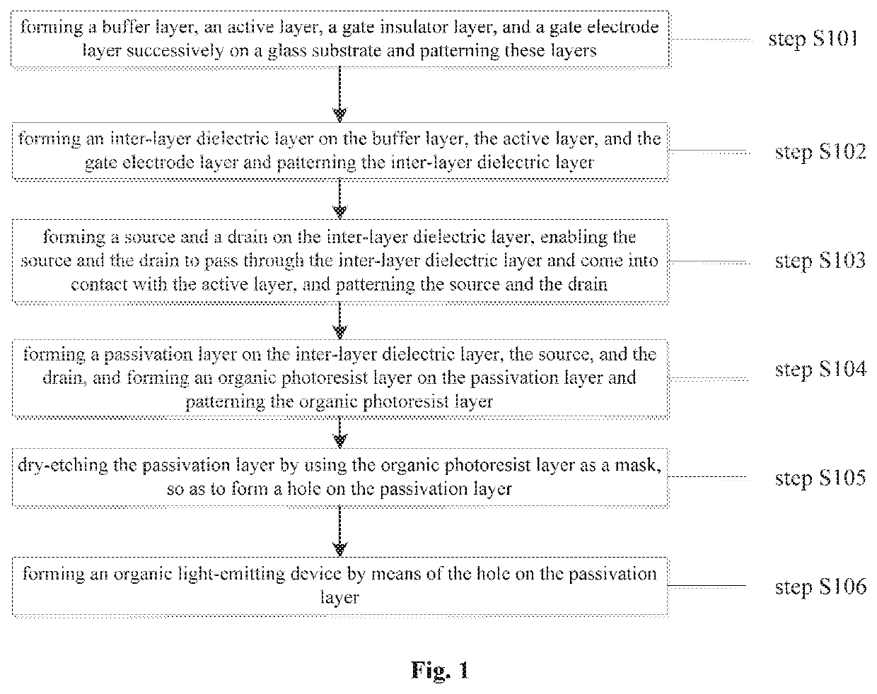
The present method for manufacturing a thin film transistor saves money and time by not requiring a separate mask to create a hole on a passivation layer. It uses an organic photoresist layer that is easier to pattern and can achieve improved product characteristics by preventing contact between the developer and exposed aluminum. This method has been developed to improve the manufacturing process of thin film transistors.

Problems solved by technology

For a conventional top-gate self-aligned structure, after a source and a drain are formed, two procedures of mold processing are required to form a passivation layer and an organic insulation film, which demands complicated techniques and a high manufacturing cost.
In a yellow photo process of the organic insulation film, TMAH, an alkaline developer, corrodes the aluminium, resulting in poor surface contact between an indium tin oxide (ITO) anode and the source and the drain, and thus affecting product characteristics.

Method used


Image

  • Method for manufacturing thin film transistor, and thin film transistor
  • Method for manufacturing thin film transistor, and thin film transistor

Examples


Embodiment Construction

[0031]The details of the present disclosure can be understood more clearly combining the description on the drawings and the embodiments. However, the specific embodiments disclosed herein are only used for illustrating the present disclosure, while cannot be understood as limiting the present disclosure in any manner. Those skilled in the art can make any deformations under the teaching of the technical content disclosed herein, and all the deformations fall into the scope of the present disclosure. The present disclosure will be further illustrated hereinafter with reference to the drawings.

[0032]The present disclosure will be described in detail hereinafter with reference to the accompanying drawings. The terms “upper”, “lower”, “right”, and “left” in the following text are directions relative to the directions shown in the drawings, and should not be construed as limiting the scope of the disclosure.

[0033]The present disclosure will be illustrated further with reference to the d...


PUM


Abstract

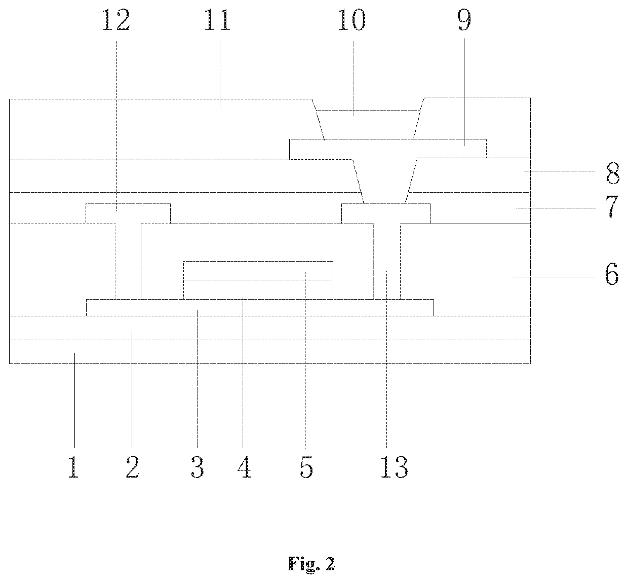
Disclosed is a method for manufacturing a thin film transistor, and a thin film transistor, relating to the technical field of liquid crystal display. The method comprises steps of: forming a buffer layer, an active layer, a gate insulator layer, and a gate electrode layer successively on a glass substrate and patterning these layers; forming an inter-layer dielectric layer on the buffer layer, the active layer, and the gate electrode layer and patterning the inter-layer dielectric layer; forming a source and a drain on the inter-layer dielectric layer, enabling the source and the drain to come into contact with the active layer, and patterning the source and the drain; forming a passivation layer and an organic photoresist layer successively on the inter-layer dielectric layer, the source, and the drain, and patterning the organic photoresist layer; dry-etching the passivation layer by using the organic photoresist layer as a mask, so as to form a hole on the passivation layer; and forming an organic light-emitting device by means of the hole on the passivation layer. The method saves a mask, requires simple techniques, and saves manufacturing costs. Besides, the developer is not able to come into direct contact with exposed aluminum of the source and the drain resulted from etching of the passivation layer. The method thus achieves the aim of improving product characteristics.

Description

CROSS-REFERENCE TO RELATED APPLICATIONS[0001]The present application claims the priority of Chinese patent application CN 201710565553.5, entitled “Method for manufacturing thin film transistor, and thin film transistor” and filed on Jul. 12, 2017, the entirety of which is incorporated herein by reference.FIELD OF THE INVENTION[0002]The present disclosure relates to the technical field of liquid crystal display, and in particular, to a method for manufacturing a thin film transistor, and a thin film transistor.BACKGROUND OF THE INVENTION[0003]Thanks to characteristics of high electron mobility, low leakage currents, low manufacturing temperature, etc., oxide semiconductors have attracted wide attention. For a conventional top-gate self-aligned structure, after a source and a drain are formed, two procedures of mold processing are required to form a passivation layer and an organic insulation film, which demands complicated techniques and a high manufacturing cost. Due to homogeneity...

Claims


Application Information

Patent Timeline
Patent Type & Authority Applications(United States)
IPC IPC(8): H01L27/12H01L51/52H01L51/56H01L29/786
CPCH01L27/1262G02F1/133603H01L29/78618H01L27/1248H01L51/5206H01L51/5237H01L27/127H01L29/7869H01L51/56H01L27/1214H01L27/1259H01L29/66742H01L29/786H01L27/1288H01L29/66969H01L27/1225H01L29/45H10K59/124H10K50/81H10K50/84H10K71/00
Inventor LI, SONGSHAN
Owner WUHAN CHINA STAR OPTOELECTRONICS TECH CO LTD
Learn More