
Thin film transistor array substrate and manufacturing method thereof

A technology of thin-film transistors and manufacturing methods, which is applied in the field of liquid crystal display, can solve the problems of destroying IGZO, complex manufacturing process, and affecting display effects, etc., and achieve the effects of good contact, saving manufacturing costs, and simplifying the manufacturing process

Pending Publication Date: 2021-06-11
KUSN INFOVISION OPTOELECTRONICS
View PDF0 Cites 1 Cited by
  • Summary
  • Abstract
  • Description
  • Claims
  • Application Information

AI Technical Summary

Problems solved by technology

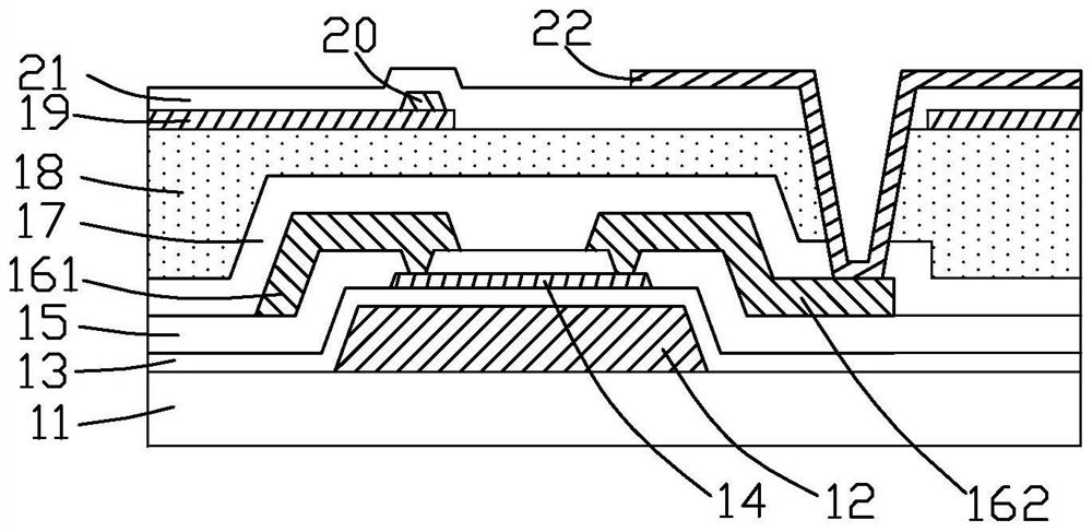
[0008] Wherein, if the ESL layer 15 is not formed on the IGZO active layer 14, the IGZO active layer 14 will be destroyed when the second metal layer is etched to form the source electrode 161 and the drain electrode 162, which will affect the display effect.
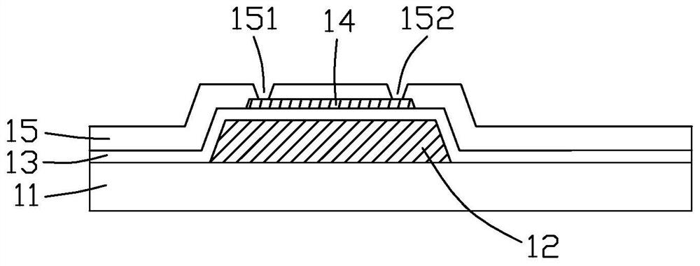
[0009] see Figure 1b As shown, the IGZO active layer 14 is covered by the ESL layer 15, which can protect the IGZO active layer 14 from being etched and damaged during the subsequent etching of the second metal layer, but for the IGZO active layer in the subsequent process The layer 14 can be connected with the source electrode 161 and the drain electrode 162, and the ESL layer 15 needs to be etched and drilled to form the first through hole 151 and the second through hole 152, so that the source electrode 161 and the drain electrode 162 pass through the first through hole respectively. The through hole 151 and the second through hole 152 are in contact with the IGZO active layer 14, and the manufacturing process is complicated
In addition, the ESL layer 15 usually uses an oxide insulating layer such as silicon oxide / alumina oxide to replace the common silicon nitride insulating layer, and the etching difficulty of the ESL layer 15 is also increased.

Method used


Image

  • Thin film transistor array substrate and manufacturing method thereof
  • Thin film transistor array substrate and manufacturing method thereof
  • Thin film transistor array substrate and manufacturing method thereof

Examples


Embodiment Construction

[0036] The aforementioned and other technical contents, features and effects of the present invention will be clearly presented in the following detailed description of preferred embodiments with reference to the drawings. Through the description of specific implementation methods, the technical means and effects of the present invention to achieve the intended purpose can be understood more deeply and specifically, but the attached drawings are only for reference and description, and are not used to explain the present invention limit.

[0037] The terms "first", "second", "third", "fourth" and the like in the description and claims of the present invention are used to distinguish similar objects, and are not necessarily used to describe a specific order or sequence .

[0038] The directional terms mentioned in the present invention, such as "upper", "lower", "front", "rear", "inner", "outer", etc., are only referring to the directions of the attached drawings, therefore, th...


PUM


Abstract

The invention discloses a thin film transistor array substrate and a manufacturing method thereof. The method comprises the steps: forming a first photoresist layer on a metal oxide thin film, carrying out exposure and development on the first photoresist layer, keeping the first photoresist layer above a grid electrode to form a first photoresist part, and removing the first photoresist layer at other positions; forming a second metal layer covering the first photoresist part on the metal oxide thin film; forming a second photoresist layer on the second metal layer, exposing and developing the second photoresist layer to form a second photoresist part and a third photoresist part which are separated from each other, and forming an opening between the second photoresist part and the third photoresist part; etching the second metal layer and the metal oxide thin film by using the second photoresist part and the third photoresist part as masks, forming a source electrode and a drain electrode which are spaced from each other after the second metal layer is etched, and forming a metal oxide active layer after the metal oxide thin film is etched; and removing the first photoresist part, the second photoresist part and the third photoresist part.

Description

technical field [0001] The invention relates to the technical field of liquid crystal display, in particular to a thin film transistor array substrate and a manufacturing method thereof. Background technique [0002] In recent years, metal oxide thin film transistors (especially IGZO TFTs) have received extensive attention in the industry due to their good electrical and optical properties. [0003] The full name of IGZO is indium gallium zinc oxide, which is called indium gallium zinc oxide in Chinese. At present, compared with low-temperature polysilicon TFT and amorphous silicon TFT, IGZOTFT has higher electron mobility, high light transmittance, low leakage current, low It has attracted extensive attention due to its advantages such as deposition temperature and low manufacturing cost. [0004] In the IGZO TFT structure, in order to prevent the etching damage of the IGZO channel, an etch stop layer (EtchStop Layer, ESL) structure is usually used to prevent the etching d...

Claims


Application Information

Patent Timeline
Patent Type & Authority Applications(China)
IPC IPC(8): H01L27/12H01L21/77
CPCH01L27/1225H01L27/1259
Inventor 严婷婷魏祥利
Owner KUSN INFOVISION OPTOELECTRONICS
Learn More