Highly integrated optical particle counter (OPC)

a technology of optical particle counter and integrated technology, applied in the field of light scattering, can solve the problems of large amount of time consumed in methods, large amount of work done, and many workers on sick leave per day, and achieve the effect of reducing the required area and large sensing area

Inactive Publication Date: 2020-01-09
CLAD INNOVATIONS LTD
View PDF0 Cites 14 Cited by
  • Summary
  • Abstract
  • Description
  • Claims
  • Application Information

AI Technical Summary

Benefits of technology

[0010]In this embodiment of the invention, the light scattering device draws a continuous sample of fluid through a light beam by means of a vacuum created with an axial or centrifugal fan. The light beam geometry may be reflected such that the beam length and geometry may be maintained while reducing the required area. The photodiode has a large sensing area, thus reducing the need for optical collection systems to collect the light scattered by entrained particles within the sensing volume. In some embodiments of the invention, an optical collection system may be included to focus the scattered light on to the photodiode.

Problems solved by technology

In addition, these conditions are a detriment to the economy, resulting in thousands of workers on sick leave per day and billions of dollars of strain on health care systems around the world.
Environmental researchers often do not have the budget to purchase multiple devices to develop data maps in order to monitor these adverse environmental conditions.
However, this method may be time consuming and often requires manual procedures.
The round inlet provides a larger cross-section and requires a lower vacuum than the rectangular profile, resulting in lower power consumption.
Although the round inlet may be simpler to implement, the circular air flow has reduced uniformity and higher variations in light intensity across the intersection of the air flow and light beam.
However, the rectangular profile may be more complex and expensive to manufacture.
One difficulty that arises may be that the velocity and volume of air flow will vary over time as a function of device location and age thus any calibration done to allow conversion to mass concentration will fail over time.
One difficulty in collection optics may be the dependency of scattered light direction on particle size.
If particles are significantly smaller than the cross-section of the light beam, they may not generate a high enough pulse to be distinguishable from signal noise.
Border zone error occurs when particles straddle the optical border of the sensing zone, resulting in only a fraction of the light to be scattered.
Coincidence error can occur with high particle number concentrations, where two or more particles are simultaneously present in the sensing zone.
Another difficulty lies in transport losses in the sampling tubing.
Current LSAS sensors are often complex and difficult to manufacture, as airborne particulate monitoring can be expensive, laborious, or inconvenient.

Method used


Image

  • Highly integrated optical particle counter (OPC)
  • Highly integrated optical particle counter (OPC)
  • Highly integrated optical particle counter (OPC)

Examples


Embodiment Construction

5.1 Enclosure

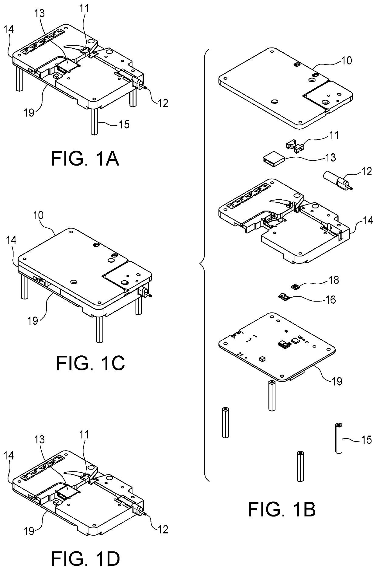
[0022]One embodiment of the enclosure may be illustrated in FIG. 1. The enclosure consists of three or more components which may be ultrasonically welded, screwed, clipped, or otherwise held together. These components may be constructed using plastic, but other materials are also suitable. The sensor in FIG. 5 may be partially or fully contained by this enclosure.

[0023]The three major components of the enclosure are the PCB 19, OPC frame 14 and the top cover 10. Other embodiments may consider just the PCB 19 and OPC frame 14. The top cover 10 may have one or more mounting / access feature for additional sensors. Other embodiments may have significantly different dimensions and geometry than shown in FIG. 1. Additional components may be used inside the enclosure other than the major components to aid in the function of the device.

[0024]Any part of the enclosure may have an engineered surface finish and / or selective metal deposition / plating for aesthetic and / or optical reas...


PUM

PropertyMeasurementUnit
focal lengthaaaaaaaaaa
flow rateaaaaaaaaaa
accelerationaaaaaaaaaa

Abstract

An apparatus and system for detecting and measuring particles entrained in an air stream. The apparatus and system include an enclosure configured to define an aerosol sampling path and an optical path. The aerosol sampling path allows an air stream having entrained particles to pass therethrough. The aerosol sampling path intersects with the optical path. The intersection defines a sensing region. The sensing region may use a band pass filter to improve signal to noise ratio. At least one flow rate sensor may be located near the sensing region. A light source provides a light beam along the optical path. The light beam intersects with the air stream in the sensing region, wherein the light beam may be scattered by entrained particles contained in the aerosol sampling path.

Description

1. FIELD OF THE INVENTION[0001]This invention relates generally to light scattering of particulate matter entrained in a fluid using optical techniques.2. BACKGROUND OF THE INVENTION[0002]There may be a growing market demand for inexpensive air quality monitors for both research and personal health. Airborne particulate matter may be among the deadliest forms of air pollution. The risk of lung cancer may be greatly increased by the concentration of particulate matter below PM10. Asthma, cardiovascular disease, respiratory diseases and birth defects have also been associated with increases in airborne particulate matter concentration. In addition, these conditions are a detriment to the economy, resulting in thousands of workers on sick leave per day and billions of dollars of strain on health care systems around the world. Environmental researchers often do not have the budget to purchase multiple devices to develop data maps in order to monitor these adverse environmental condition...

Claims


Application Information

Patent Timeline
Patent Type & Authority Applications(United States)
IPC IPC(8): G01N15/02G01N15/06G01N15/14G01N21/53
CPCG01N15/0205G01N2015/0046G01N21/53G01N2015/1486G01N15/06G01N15/1459G01N15/10
Inventor LAVROVSKY, VLADISLAV IGOREVICHCOOPER, TAYLORMACDONALD, AARON JOSEPH
Owner CLAD INNOVATIONS LTD
Why Eureka
Try Eureka