Powder bed fusion apparatus and methods

a technology of fusion apparatus and powder bed, which is applied in the direction of additive manufacturing process, manufacturing tools, applying layer means, etc., can solve the problems of unsuitable metal powder system, unsolidified powder is either removed or required manual intervention through glove box

Active Publication Date: 2020-01-16
RENISHAW PLC
View PDF0 Cites 8 Cited by
  • Summary
  • Abstract
  • Description
  • Claims
  • Application Information

AI Technical Summary

Benefits of technology

[0017]The mechanical manipulator may be arranged to invert the object, for example by tilting the object by more than 90 degrees from an as built orientation of the object and preferably, by 180 degrees. In this way, powder that may be otherwise trapped in the object may be freed. The mechanical manipulator may be arranged to rotate the object about two, preferably orthogonal, axes. Both axes may be non-orthogonal to the working plane. Alternatively, a first one of the axes may be non-orthogonal to the working plane and a second one of the axes substantially orthogonal to the working plane. The mechanical manipulator may be operable to tilt the object about the first axis when the mechanical manipulator is in at least two orientations about the second axis such that the object can be tilted about the first axis with the object in different positions relative to the first axis. This may help to free powder form internal channels/recesses in the object.
[0018]The mechanical manipulator may be mounted in the apparatus such that the build platform has to be lowered from an engagement position in which the mechanical manipulator engages with the object and/or build substrate to provide room for rotation of the mechanical manipulator engaged with the object and/or build sub...

Problems solved by technology

A problem with such powder bed fusion apparatus is how to extract the workpiece from the powder bed after completion of the build.
A problem with such an apparatus is that it requires manual intervention through a glove box.
Such a system is particularly unsuitable for use with metal powder as a workpiece built from metal powder typically must be secured to a solid substrate plate, for ...

Method used


Image

  • Powder bed fusion apparatus and methods
  • Powder bed fusion apparatus and methods
  • Powder bed fusion apparatus and methods

Examples


Embodiment Construction

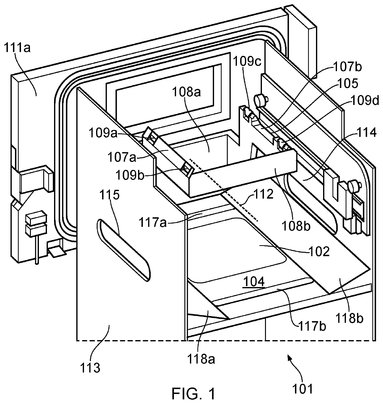
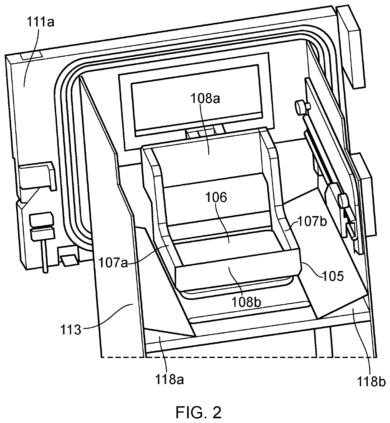
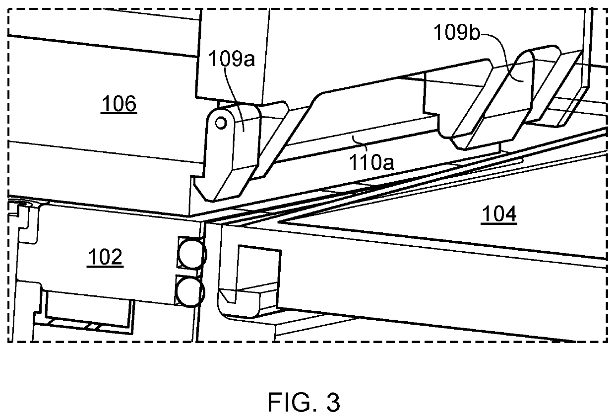
[0084]Referring to FIGS. 1 to 6, a powder bed fusion apparatus 101 according to one embodiment of the invention comprises a build platform 102 movable within a build sleeve 103 to define a build volume, a layer formation device (not shown) for forming layers of powder across the build volume in a working plane and an irradiation device (not shown) for irradiating powder in the working plane to selectively fuse the powder. Successive formation of powder layers forms a powder bed in the build volume. The powder formation device typically comprises a doser (not shown) for dosing powder and a wiper (not shown) for spreading the dosed powder into a layer. In this embodiment, the doser is a top-doser, which doses powder onto surface 104.

[0085]A build chamber 113 is provided for maintaining an inert atmosphere surrounding the working surface of the powder bed. The build chamber 113 may comprise an upper and lower chamber as described in WO2010 / 007394. Doors 111a and 111b provide access to ...


PUM

PropertyMeasurementUnit
Forceaaaaaaaaaa
Volumeaaaaaaaaaa

Abstract

A powder bed fusion apparatus for building an object in a layer-by-layer manner includes a build platform movable within a build sleeve to define a build volume, a layer formation device for forming layers of powder across the build volume in a working plane and an irradiation device for irradiating powder in the working plane to selectively fuse the powder. The powder bed fusion apparatus further includes a mechanical manipulator arranged to engage with the object and/or a build substrate, to which the object is attached, to tilt the object in a raised position above the working plane such that powder is freed from the object and deposited at a location above the working plane and/or into the build volume.

Description

FIELD OF INVENTION[0001]This invention concerns powder bed fusion apparatus and methods in which selected areas of a powder bed are solidified in a layer-by-layer manner to form a workpiece. The invention has particular, but not exclusive application, to selective laser melting (SLM) and selective laser sintering (SLS) apparatus.BACKGROUND[0002]Powder bed fusion apparatus produce objects through layer-by-layer solidification of a material, such as a metal powder material, using a high energy beam, such as a laser or electron beam. A powder layer is formed across a powder bed contained in a build sleeve by lowering a build platform to lower the powder bed, depositing a heap of powder adjacent to the lowered powder bed and spreading the heap of powder with a wiper across (from one side to another side of) the powder bed to form the layer. Portions of the powder layer corresponding to a cross-section of the workpiece to be formed are then solidified through irradiating these areas with...

Claims


Application Information

Patent Timeline
IPC IPC(8): B29C64/241B29C64/245B29C64/205B29C64/268B29C64/371B29C64/321
CPCB33Y30/00B29C64/205B29C64/268B33Y40/00B29C64/241B29C64/321B29C64/245B29C64/371B29C64/153B29C64/35B29C64/379Y02P10/25B22F10/28B22F10/68B22F12/30B22F12/88B22F10/73B22F10/32B22F12/33B22F12/80B22F12/82B22F12/37
Inventor MCMURTRY, DAVID ROBERTSSUTCLIFFE, CHRISTOPHERWESTON, ROBIN GEOFFREYCAMPTON, PAULWHITTON, DAVID JOHNBEEBY, DAVID
Owner RENISHAW PLC
Why Eureka
Try Eureka