Fuel cell system
a fuel cell and system technology, applied in the field of fuel cell systems, can solve the problems of larger apparatus size, and achieve the effect of reducing the size of the fuel cell system and eliminating the need for a pump or the like for pumping water to the cooling devi
- Summary
- Abstract
- Description
- Claims
- Application Information
AI Technical Summary
Benefits of technology
Problems solved by technology
Method used
Image
Examples
first embodiment
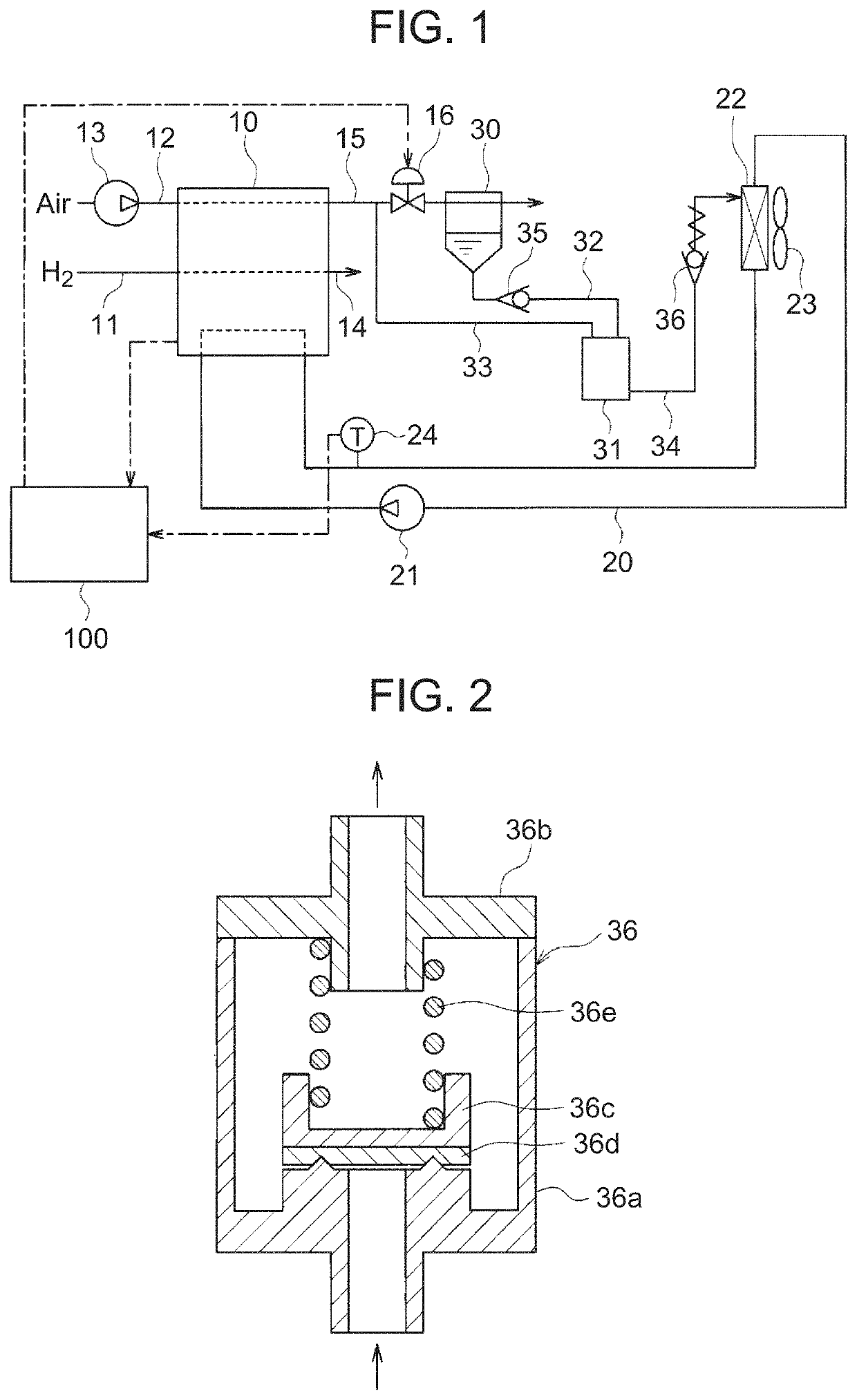
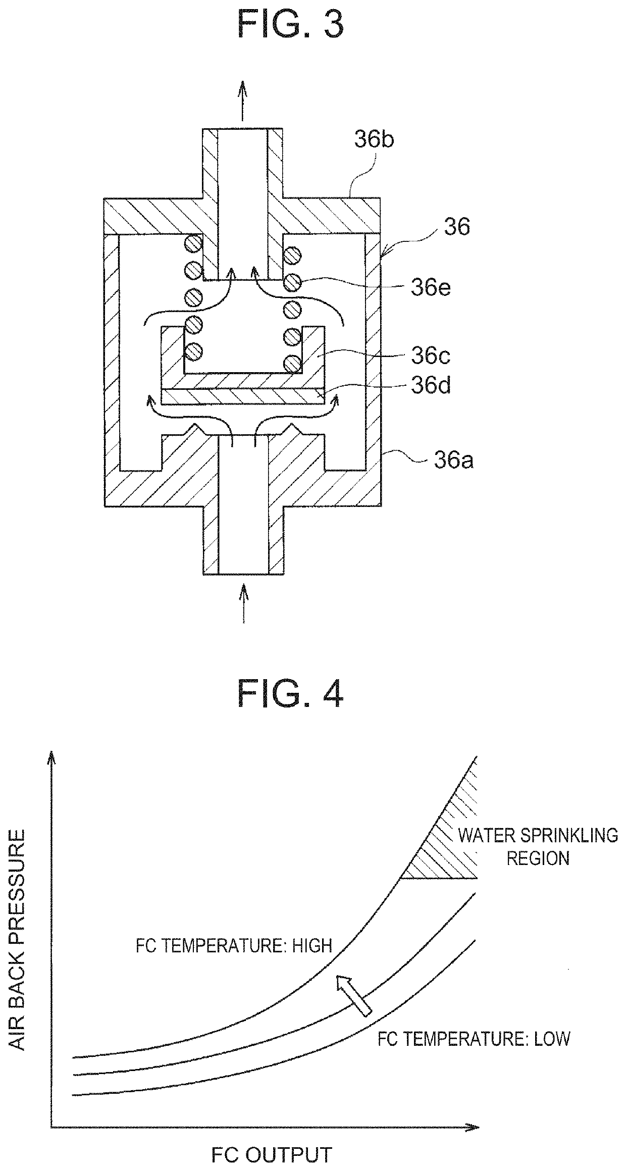
[0032]Hereinafter, a first embodiment of the present disclosure will be described based on FIGS. 1 to 4. FIG. 1 is a view showing an entire configuration of a fuel cell system according to the first embodiment. This fuel cell system is applied to a so-called fuel cell vehicle, which is a type of an electric vehicle, and supplies electric power to an electric load, such as an electric motor for vehicle traveling.
[0033]As shown in FIG. 1, the fuel cell system includes a fuel cell 10 that generates electric power by using an electrochemical reaction between hydrogen and oxygen. The fuel cell 10 is configured to supply electric power to electric equipment such as an inverter (not shown). The inverter converts direct current supplied from the fuel cell 10 into alternating current and supplies this current to a motor for traveling (load) to drive the motor.
[0034]In the first embodiment, a solid polymer electrolyte fuel cell is used as the fuel cell 10, and it has a stack structure in whic...
second embodiment
[0062]Next, a second embodiment of the present disclosure will be described. Hereinafter, only differences from the first embodiment will be described.
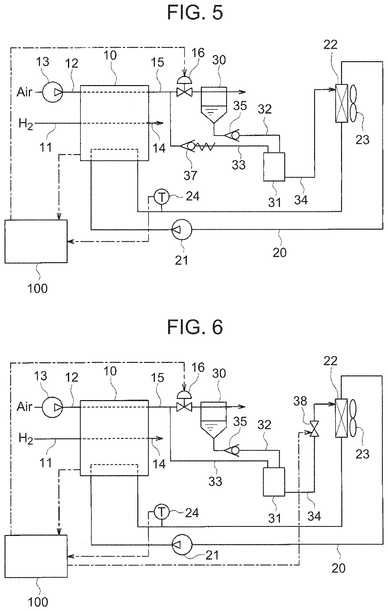
[0063]As shown in FIG. 5, in the second embodiment, the water sprinkling passage 34 is not provided with the water sprinkling control valve 36, and the high pressure introduction passage 33 is provided with an air control valve 37. The air control valve 37 is a pressure control valve configured to close when the pressure of the air exhaust gas supplied from the air discharge passage 15 to the high pressure introduction passage 33 becomes smaller than a predetermined pressure, and to open when this pressure of the air exhaust gas becomes greater than the predetermined pressure. The water sprinkling passage 34 and the air control valve 37 correspond to the sprinkling device of the present embodiment.
[0064]In the fuel cell system of the second embodiment, the air control valve 37 is configured to open when the air back pressure of the fu...
third embodiment
[0066]Next, a third embodiment of the present disclosure will be described. Hereinafter, only differences from the above respective embodiments will be described.
[0067]As shown in FIG. 6, in the third embodiment, the water sprinkling passage 34 is provided with a water sprinkling control valve 38. The water sprinkling control valve 38 of the third embodiment is configured as a flow rate control valve capable of adjusting a flow of the water flowing through the water sprinkling passage 34 at any flow rate by appropriately adjusting the valve opening degree of the valve. The water sprinkling control valve 38 operates based on a control signal from the control unit 100. The water sprinkling passage 34 and the water sprinkling control valve 38 correspond to the sprinkling device of the present embodiment.
[0068]The control unit 100 may be configured to control the water sprinkling control valve 38 to open when the outlet temperature of the fuel cell 10 becomes higher than a predetermined...
PUM
| Property | Measurement | Unit |
|---|---|---|
| pressure | aaaaa | aaaaa |
| temperature | aaaaa | aaaaa |
| electric power | aaaaa | aaaaa |
Abstract
Description
Claims
Application Information
 - R&D
- Intellectual Property
- Life Sciences
- Materials
- Tech Scout
- Unparalleled Data Quality
- Higher Quality Content
- 60% Fewer Hallucinations
Browse by: Latest US Patents, China's latest patents, Technical Efficacy Thesaurus, Application Domain, Technology Topic, Popular Technical Reports.
© 2025 PatSnap. All rights reserved.Legal|Privacy policy|Modern Slavery Act Transparency Statement|Sitemap|About US| Contact US: help@patsnap.com


