Ion source device

a source device and ion source technology, applied in the direction of electrical discharge tubes, particle separator tubes, electrical apparatus, etc., can solve the problems of reducing brightness, limited choice of common ion species, and inability to provide high-brightness ion beams comparable, etc., to achieve rapid switching between different ion species, high brightness, and flexibility in the creation of ion species

Active Publication Date: 2020-02-27
LUXEMBOURG INST OF SCI & TECH LIST
View PDF6 Cites 1 Cited by
  • Summary
  • Abstract
  • Description
  • Claims
  • Application Information

AI Technical Summary

Benefits of technology

[0033]The present invention suggests an architecture for building an electron impact ion source, which unlike conventional architectures, allows generating ion beams of high brightness, while leveraging at least one known advantage linked to electron impact sources, i.e., flexibility regarding the created ion species and the ability to rapidly switch between different ion species. An electron beam enters an ionization chamber into which a gas that is to be ionized is fed at relatively high pressure. Due to the high pressure, the number of gas molecules is increased as compared to known EI source architectures. This allows increasing the probability of interaction between the electron beam and the gas, yielding a large number of ions. The created ions are then extracted from the ionization chamber, in a direction that is coaxial to the electron beam, by means of an ion carpet funnel, to form an ion beam. The electron beam is transported at high energy along the major part of the electron beam guiding structure in order to obtain an efficient electron beam transmission into the ionization chamber. Only in close vicinity of and within the ionization chamber the electron beam is retarded in order to obtain a high ionization efficiency. Advantageously the electron beam is stopped within the ionization chamber, so that it does not hit the ion carpet's electrodes in order to keep the charge deposition on the electrodes as low as possible. The use of an ion carpet within the ionization chamber allows yielding a high ion beam current, yet at the same time it keeps the physical dimensions of the ionization chamber, and indeed of the ion source device, small. This renders the device according to the invention particularly useful for any applications which do not only require a high brightness ion beam, but also a small-footprint ion source device.

Problems solved by technology

Both sources can provide ion beams with reasonable lifetimes but unfortunately they are limited in the commonly available choice of ion species.
Unfortunately, so far these sources do not provide high-brightness ion beams comparable to the LMIS or GFIS.
Due to the large ionization volume and the extraction mechanism, the reduced brightness as defined here above of such known EI source devices is limited, and typically of the order of 1 A m−2 sr−1 V−1.

Method used


Image

  • Ion source device

Examples


Embodiment Construction

[0038]This section describes the invention in further detail based on preferred embodiments and on the figures. Similar reference numbers will be used to describe similar or the same concepts throughout different embodiments of the invention. For example, references 100 and 200 respectively denote two different embodiments of the ion source device in accordance with the invention.

[0039]It should be noted that features described for a specific embodiment described herein may be combined with the features of other embodiments unless the contrary is explicitly mentioned.

[0040]Features commonly known in the art will not be explicitly mentioned for the sake of focusing on the features that are specific to the invention. For example, the ion source device in accordance with the invention is evidently powered by an electric supply, even though such supply is not explicitly referenced on the figures nor referenced in the description.

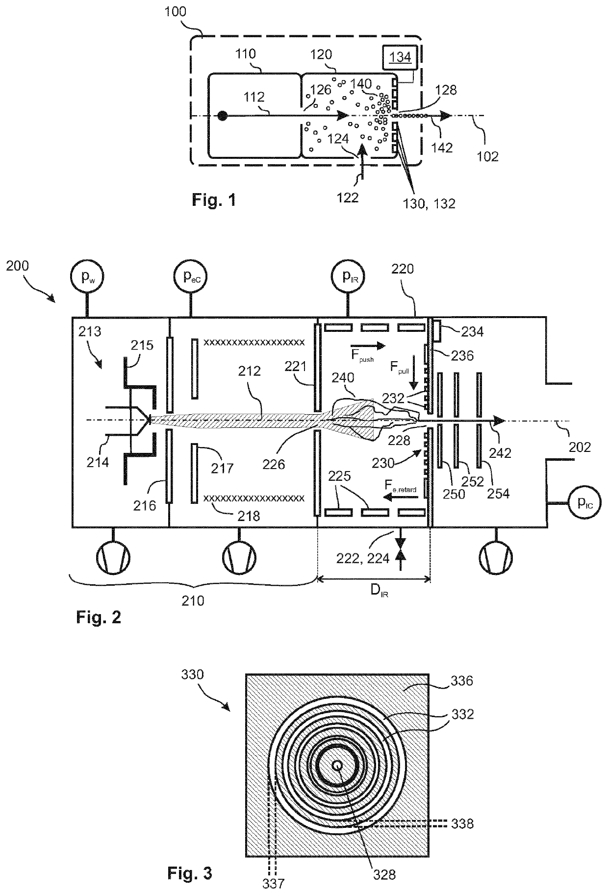
[0041]FIG. 1 shows an ion source device 100 in accordance ...


PUM


Abstract

The invention provides an electron-impact ion source device having high brightness as compared to known Nier-type ion sources, while providing similar advantages in terms of flexibility of the generated ion species, for example. The ionization chamber of the device operates at high pressures and provides for a large number of interactions between the electron beam and the gas molecules.

Description

TECHNICAL FIELD[0001]The invention lies in the field of ion source devices, for use in Focused Ion Beam applications such as FIB machining, imaging or sample analysis, for example by mass spectrometry.BACKGROUND OF THE INVENTION[0002]Focused Ion Beam, FIB, technology finds its application in three major activities, all three of which rely on the availability and use of finely focused ion beams.[0003]FIB machining allows the manufacture of small nano-scale devices, for example through milling of materials. It further allows functionalizing surfaces with specific properties or creating nano-materials. FIB machining is further used as a sample preparation tool, e.g. for Transmission Electron Microscopy, TEM.[0004]FIBs are also used in nano-imaging in order to perform three-dimensional sample investigations at the nanoscale. A well-established tool in this application field is the ORION™ Helium Ion Microscope, HIM. It uses He+ and Ne+ beams to perform high resolution ion-microscopy by d...

Claims


Application Information

Patent Timeline
Patent Type & Authority Applications(United States)
IPC IPC(8): H01J37/08H01J37/147H01J37/12H01J37/30
CPCH01J2237/082H01J2237/31749H01J37/147H01J37/3007H01J2237/1504H01J37/12H01J37/08H01J27/205H01J2237/062H01J49/066
Inventor DE CASTRO, OLIVIERDELLA-NEGRA, SERGEDOWSETT, DAVIDWIRTZ, TOM
Owner LUXEMBOURG INST OF SCI & TECH LIST
Why Eureka
Try Eureka