Plant and method for generation of synthesis gas

a technology of synthesis gas and plant, which is applied in the direction of combustible gas purification/modification, hydrogen separation using liquid contact, and separation process, etc., can solve the problems of high electrical energy expenditure and the method, and achieve the effect of reducing the energy expenditure for compression

Active Publication Date: 2020-03-19
LAIR LIQUIDE SA POUR LETUDE & LEXPLOITATION DES PROCEDES GEORGES CLAUDE
View PDF0 Cites 2 Cited by
  • Summary
  • Abstract
  • Description
  • Claims
  • Application Information

AI Technical Summary

Benefits of technology

[0020]The cooling water which is cooled in the evaporative cooler is fed to the method or to the plant from the outside, for example from a cooling water supply system which is not part of the scope of the invention, and, after use, recycled back to it from the plant according to the invention.
[0021]In the evaporative cooler, the cooling water is contacted with the tail gas stream and / or the expanded nitrogen stream. It is possible here to use means known to those skilled in the art, such as structured packings or random packings.
[0022]A preferred configuration of the invention is characterized in that the nitrogen stream generated by air fractionation, before it is used for evaporative cooling of the cooling water, is expanded by means of a turbine, cooled simultaneously, and then used to cool the coolant in the coolant circuit of the compression refrigeration plant. In this way, the pressure potential present in this stream is also exploited to support the compression refrigeration plant, and the energy expenditure for the compression is lowered.

Problems solved by technology

The method entails high expenditure of electrical energy, especially in the steps of production of the gasifying agent by air fractionation and removal of the acid gas, for example for the compression of air for the air fractionation and the compression of the coolant in the compression cooling plant for refrigeration of the absorbent.

Method used


Image

  • Plant and method for generation of synthesis gas
  • Plant and method for generation of synthesis gas

Examples


Embodiment Construction

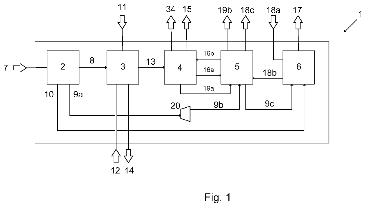
[0027]In FIG. 1, the plant 1 according to the invention comprises the component plants of cryogenic air fractionation 2, gasification 3, Rectisol plant 4, compression refrigeration plant 5 and the evaporative cooling plant 6. Air 7 is sucked in from the environment and fractionated in the air fractionation 2 into an oxygen stream 8, a nitrogen stream 9a and a tail gas stream 10. The gasification plant 3 is supplied with carbonaceous fuel 11, and it is converted therein with the oxygen stream 8 and steam 12 supplied to the plant to crude synthesis gas 13 and ash 14. The crude synthesis gas 13 generated is fed to the Rectisol plant 4, where the acid gases hydrogen sulfide 34 and carbon dioxide 19 are removed by cryogenic absorption with methanol as absorbent. The hydrogen sulfide removed is discharged from the plant 1 as stream 34 and the cleaned synthesis gas as stream 15 for further treatment. The carbon dioxide 19a removed is used for cooling in the coolant circuit of the compressi...


PUM

PropertyMeasurementUnit
pressureaaaaaaaaaa
temperatureaaaaaaaaaa
pressureaaaaaaaaaa

Abstract

Method and plant for generation of synthesis gas, comprising the steps of air fractionation to give oxygen, nitrogen and tail gas, gasification of a hydrocarbonaceous fuel to give crude synthesis gas and cleaning of the crude synthesis gas by removal of acid gas by means of cryogenic absorption, wherein the absorbent is cooled by means of a compression coolant circuit and the cooling water used is cooled by evaporative cooling by means of the tail gas obtained in the air fractionation.

Description

CROSS REFERENCE TO RELATED APPLICATIONS[0001]This application is a § 371 of International PCT Application PCT / EP2017 / 025340, filed Nov. 20, 2017, which claims the benefit of EP16400057.2, filed Dec. 9, 2016, both of which are herein incorporated by reference in their entireties.FIELD OF THE INVENTION[0002]The invention relates to a method of generating a synthesis gas which consists mainly of carbon monoxide and hydrogen and has been freed of acid gases, proceeding from a hydrocarbonaceous fuel, and also air and steam, comprising the following method steps:[0003]fractionating air by low-temperature rectification to give an oxygen stream, a tail gas stream and a nitrogen stream, wherein the tail gas stream and the nitrogen stream are at ambient temperature and the nitrogen stream is at elevated pressure,[0004]converting a hydrocarbonaceous fuel at elevated pressure and elevated temperature with the oxygen stream and the steam, by a method known to those skilled in the art, to a synth...

Claims


Application Information

Patent Timeline
Patent Type & Authority Applications(United States)
IPC IPC(8): C01B3/36C01B3/02C01B3/52C10K1/00B01D53/14B01D53/18F25J3/04
CPCF25J3/04545C01B3/36C01B2203/0415C01B3/52C01B2203/0233B01D2252/2021C01B3/02F25J2240/12C10K1/004C10K1/005C01B2203/0485B01D53/1462B01D53/18C01B2203/1241F25J2260/44B01D53/1493C01B2203/0261C01B2203/0475F25J2205/34F25J3/04563C01B3/506C10J2300/165B01D53/14C01B3/50F25J3/04
Inventor CHAUBET, LUCIEBONNE, FREDERICBOUET, CAMILLESCHLICHTING, HOLGERWAGNER, MARC
Owner LAIR LIQUIDE SA POUR LETUDE & LEXPLOITATION DES PROCEDES GEORGES CLAUDE
Why Eureka
Try Eureka