A dynamically adaptive combined heat and power system and method thereof

a combined heat and power system technology, applied in the field of energy conversion systems, can solve the problems of low quality heat, inconvenient recovery and use in secondary systems or processes, and inconvenient recovery of conventional heat, so as to optimise the energy efficiency and cost effectiveness of the system, and improve the overall energy efficiency

Active Publication Date: 2020-03-19
ENCORA TECH LTD
View PDF0 Cites 8 Cited by
  • Summary
  • Abstract
  • Description
  • Claims
  • Application Information

AI Technical Summary

Benefits of technology

[0025]Advantageously, the combined heat and power system may further comprise at least one second heat exchanger operatively coupled to and arranged downstream from said at least one first heat exchanger. Preferably, said at least one second heat exchanger may be adapted to transfer thermal energy to said at least one selectively variable second thermal energy store. Even more preferably, said at least one second heat exchanger may be operatively coupled to said at least one selectively variable second thermal energy store via a third heat exchanger. This provides the advantage of improving the energy efficiency even further by recovering low-grade thermal energy that may be rejected when recovering the high-grade thermal energy of, for example, the exhaust gases of the engine.
[0026...

Problems solved by technology

38, which in most conventional cases is not suitable for recovery and use in the secondary systems or processes 28.
There may be instances where such low-grade heat is theoretically suitable for direct use in a facility, however, practical limitations associated with the cost or complexity of using such low temperature heat (also referred to as low-quality heat) prevent its use.
However, the size and capacity of the conventional heat store that is necessary to optimise a typical CHP system 10 can be very la...

Method used


Image

  • A dynamically adaptive combined heat and power system and method thereof
  • A dynamically adaptive combined heat and power system and method thereof
  • A dynamically adaptive combined heat and power system and method thereof

Examples


Embodiment Construction

)

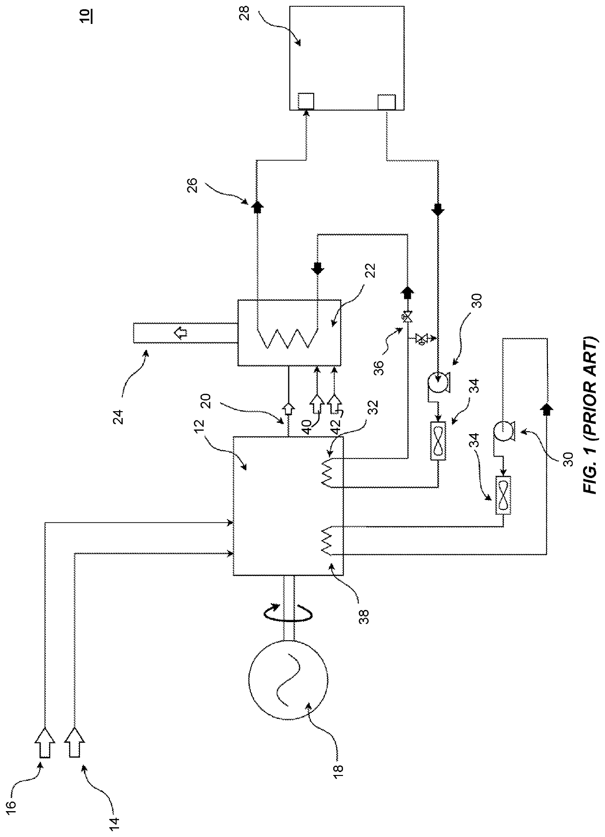
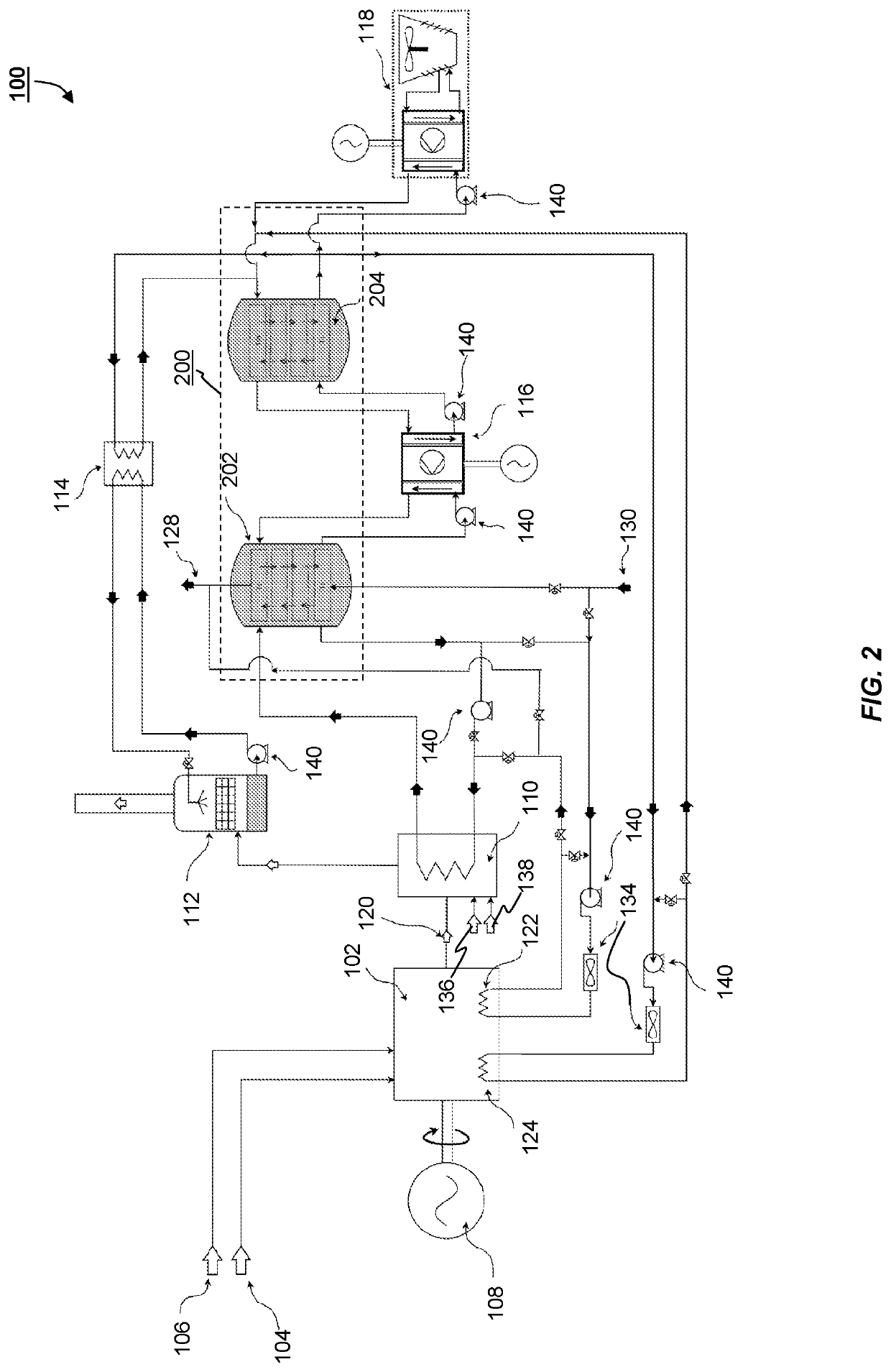
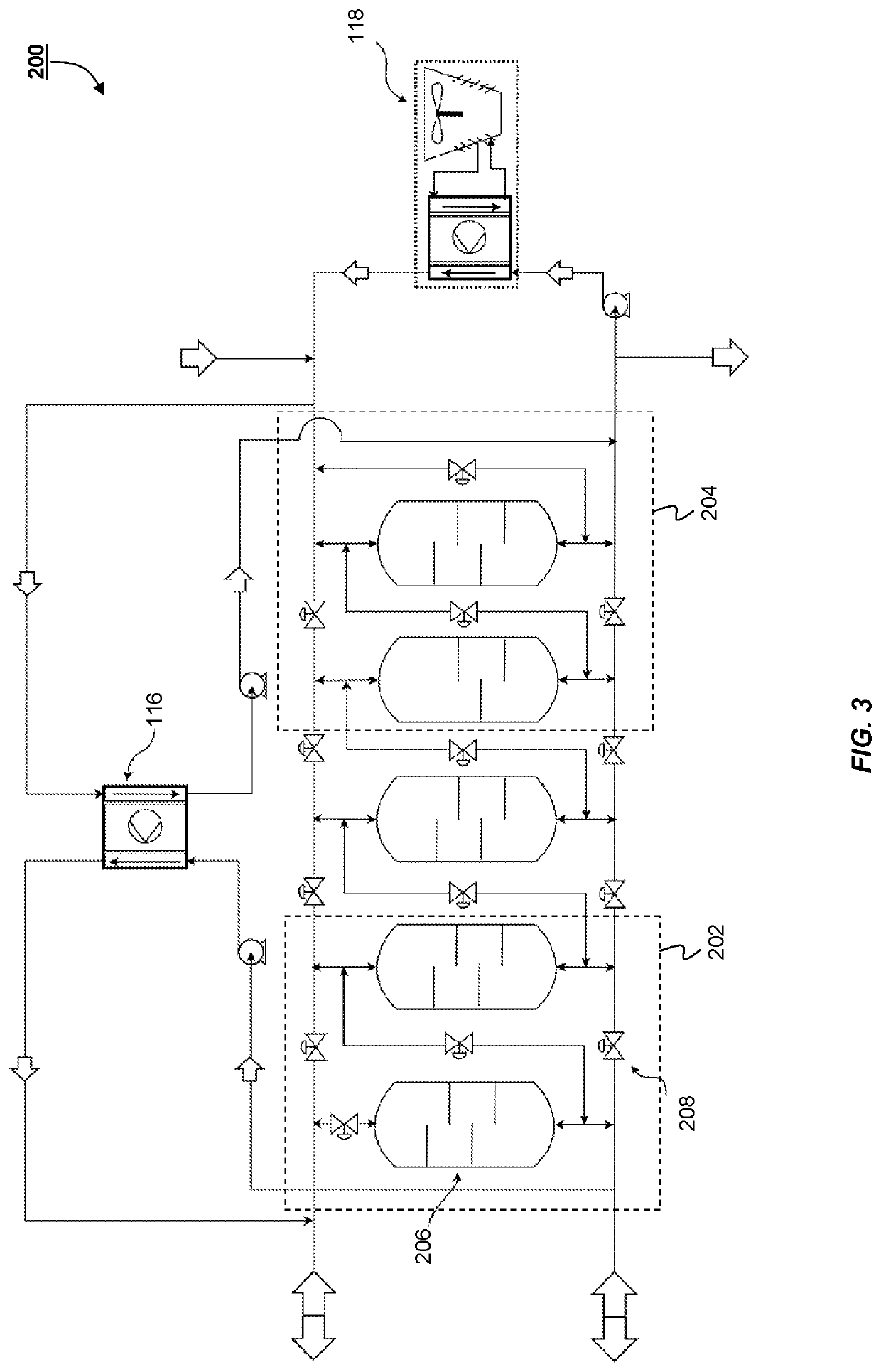
[0045]The exemplary embodiments of this invention will be described in relation to a combined heat and power system having at least one engine coupled to an electric generator, so as to generate and supply electricity, as well as, thermal energy to at least one consumer, such as, for example a university campus. However, it should be appreciated that, in general, the system and method of this invention is equally applicable to any other suitable cogeneration arrangement.

[0046]For purposes of explanation, it should be appreciated that the terms ‘thermal energy’, ‘heat’ and ‘heat energy’ are used interchangeably throughout the description. In addition, the term ‘real-time’ when linked to any information or data provided from an external source is understood to mean momentarily valid, current or effective within a relatively short predetermined period of time until that information is updated. Furthermore, the terms ‘heat exchanger’ and ‘heat recovery unit’ are used interchangeably. T...


PUM


Abstract

The present invention provides for a combined heat and power system, comprising: at least one engine, operatively coupled to a generator, having at least one first heat source adapted to provide a first thermal energy output at a first temperature range, and at least one second heat source adapted to provide a second thermal energy output at a second temperature range; at least one first heat exchanger, operatively coupled to said at least one engine, and adapted to selectively receive and transfer at least a portion of any one or all of said first thermal energy output and said at least one second thermal energy output; and a dynamically adaptive heat storage system. The dynamically adaptive heat storage system further comprises: a selectively variable first thermal energy store, adapted to accept, store and discharge thermal energy at said first temperature range; at least one selectively variable second thermal energy store, adapted to accept, store and discharge thermal energy at said second temperature range; at least one first heat pump, operatively coupled to said first thermal energy store and said at least one second thermal energy store, and which is adapted to transfer and thermally upgrade the thermal energy stored in said at least one second thermal energy store to said first thermal energy store, and a system controller, adapted to selectively engage any one or all of said at least one first heat source and said at least one second heat source and control the amount of thermal energy that is stored, upgraded or discharged, so as to optimise the energy efficiency of said combined heat and power system.

Description

[0001]The present invention generally relates to energy conversion systems and, in particular, to combined heat and power energy systems including thermal energy storage systems.INRODUCTION[0002]Engines of various types that may use a fuel to generate power and produce heat as a by-product are commonly used in a variety of combined heat and power systems (CHP), also known as cogeneration systems. FIG. 1 shows a schematic illustration of a typical arrangement for such a combined heat and power (CHP) system 10. Here, one or more piston engine(s) 12 are supplied with a stream of air 14 and fuel 16. The engines 12 are operatively coupled to one or more electrical generators 18. Exhaust gases 20 are discharged from the engine(s) 12, usually at a high temperature (typically >400° C.), and are provided to a heat recovery unit 22 (e.g. heat exchanger). In the heat recovery unit 22, a proportion of the comprised heat energy is removed from the exhaust gases 20, thereby cooling the exhaust...

Claims


Application Information

Patent Timeline
IPC IPC(8): F25B27/02F02G5/02F24D11/02F25B25/00F25B49/02F24D5/12F24D18/00
CPCF25B27/02F25B25/005F24H2240/06F02G5/02F24D5/12F25B49/02F24D2200/26F24D11/0235F25B2339/047Y02B30/52Y02B10/70Y02P80/15Y02A30/274F24D18/00F24D2101/70F24D2103/17F24D2103/13F02G5/04
Inventor WATSON, DARRENCLANCY, DAVID
Owner ENCORA TECH LTD
Why Eureka
Try Eureka