
Laminated film and display device including same

a technology of laminated film and display device, which is applied in the direction of instruments, other domestic objects, synthetic resin layered products, etc., can solve the problems of glass being easily broken, suitable for a flexible display device, fragile glass, etc., and achieve excellent appearance quality and improve optical characteristics and visibility.

Active Publication Date: 2020-04-09
SAMSUNG ELECTRONICS CO LTD +1
View PDF0 Cites 0 Cited by
  • Summary
  • Abstract
  • Description
  • Claims
  • Application Information

AI Technical Summary

Benefits of technology

The patent text describes a laminated film that reduces interference and reflection to improve optical quality and visibility. This film can be used as a window for flexible display devices, enhancing their appearance. The technical effect is to provide a better visual experience for users and improve the overall quality of flexible display devices.

Problems solved by technology

However, glass is fragile and is easily broken by the exterior impact, when applied to a portable display device or the like, and also glass is not flexible, so it may be not suitable for a flexible display device.

Method used


Image

  • Laminated film and display device including same
  • Laminated film and display device including same
  • Laminated film and display device including same

Examples


synthesis example 1

Preparation of Amide Structural Unit-Containing Oligomer

[0225]According to Reaction Scheme 1, an amide structural unit-containing oligomer which forms an aramid structure having amino groups at both ends by polymerizing TFDB (2,2′-bis(trifluoromethyl)benzidine) and TPCL (terephthaloyl chloride) is prepared.

[0226]Particularly, 1 molar equivalent (0.122 mol, 39.2 g) of 2,2′-bis(trifluoromethyl)benzidine (TFDB) and 2.8 molar equivalent (0.343 mol, 27.11 g) of pyridine were dissolved in 700 g of N,N-dimethylacetamide (DMAC) in a round-bottom flask, and then the residual TFDB was completely dissolved by further adding 50 ml of dimethyl acetamide. 0.7 molar equivalent (0.086 mol, 17.4 g) of terephthaloyl chloride (TPCl) was added in four portions and vigorously stirred for 15 minutes.

[0227]The resultant solution is stirred under the nitrogen atmosphere for 2 hours, and then added into 7 L of a NaCl solution containing 350 g of NaCl and stirred for 10 minutes. The solid is filtered and re-...

preparation examples 1 to 4

Preparation of Polyimide-Based Copolymer Solution for Optical Enhancement Layer

preparation example 1

Preparation of Poly(imide-urethane) Copolymer Solution

[0228]2.52 g (0.0279 mol) of butanediol (BD) and 12.4 g (0.0559 mol) of isophorone diisocyanate (IPDI), and DBTDL (dibutyltin dilaurate) are added into 250 ml of 4-neck double wall reactor equipped with a mechanical agitator and a nitrogen inlet, the temperature is slowly increased to 70° C., and the reaction mixture is stirred at 70° C. for 4 hours to be reacted. After completing the reaction, the reactor is cooled to 25° C., and 94 g of dimethyl acetamide (DMAc), 8.95 g (0.0279 mol) of 2,2′-bis(trifluoromethyl)benzidine (TFDB), 2.46 g (0.0084 mol) of 3,3′,4,4′-biphenyltetracarboxylic dianhydride (BPDA), and 8.70 g (0.0196 mol) of 2,2-bis-(3,4-dicarboxyphenyl hexafluoropropane dianhydride) (6FDA) are added and stirred for 24 hours. Then, 2.3 g of pyridine and 7.9 g of acetic anhydride are added and stirred for 24 hours to provide a poly(imide-urethane) copolymer solution having a solid content of 25 wt %.


PUM

PropertyMeasurementUnit
refractive indexaaaaaaaaaa
thicknessaaaaaaaaaa
thicknessaaaaaaaaaa

Abstract

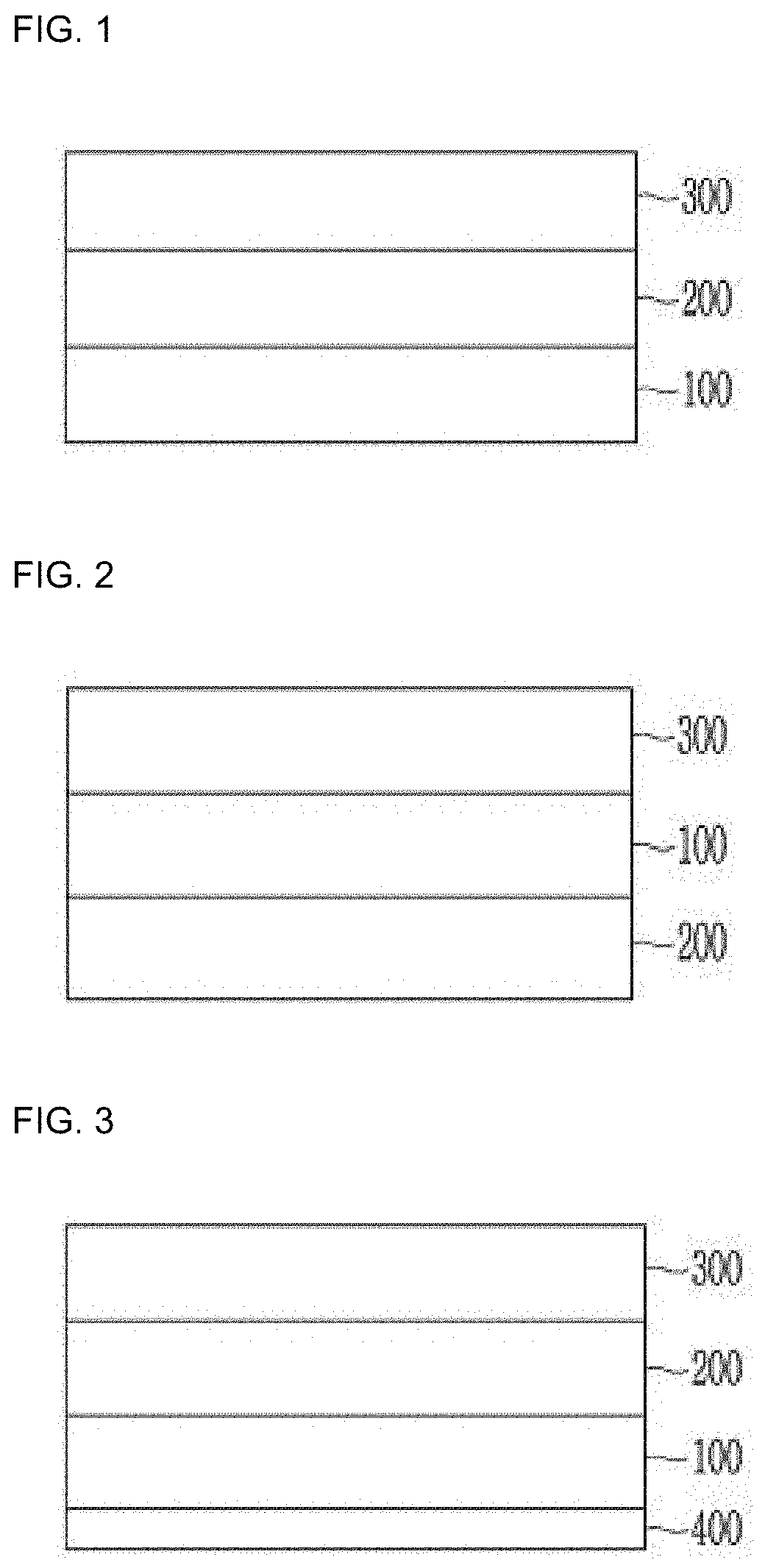
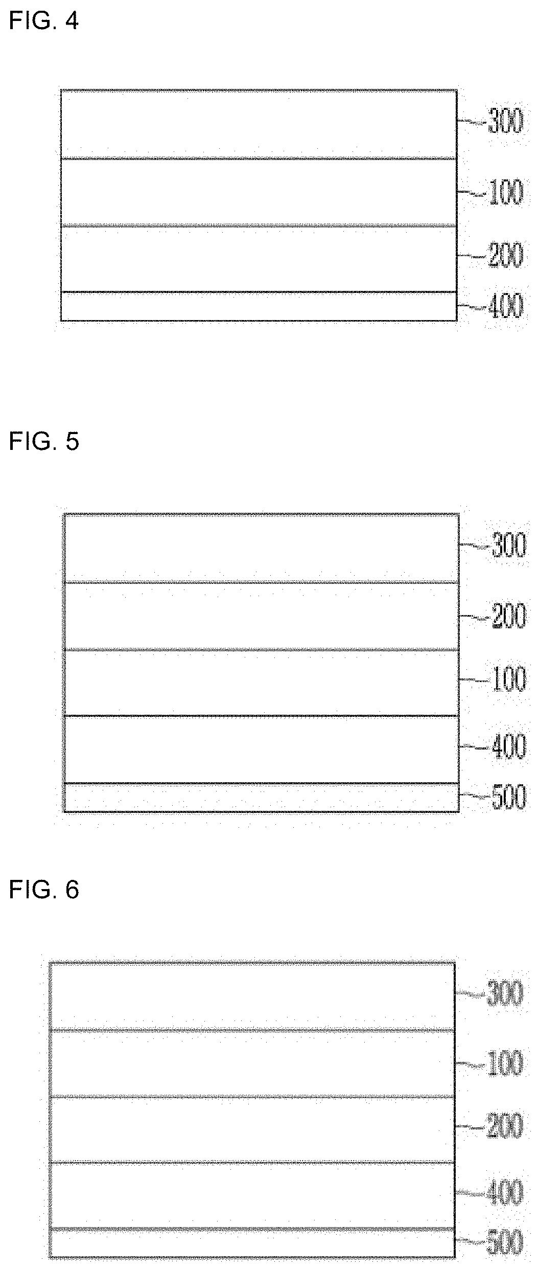
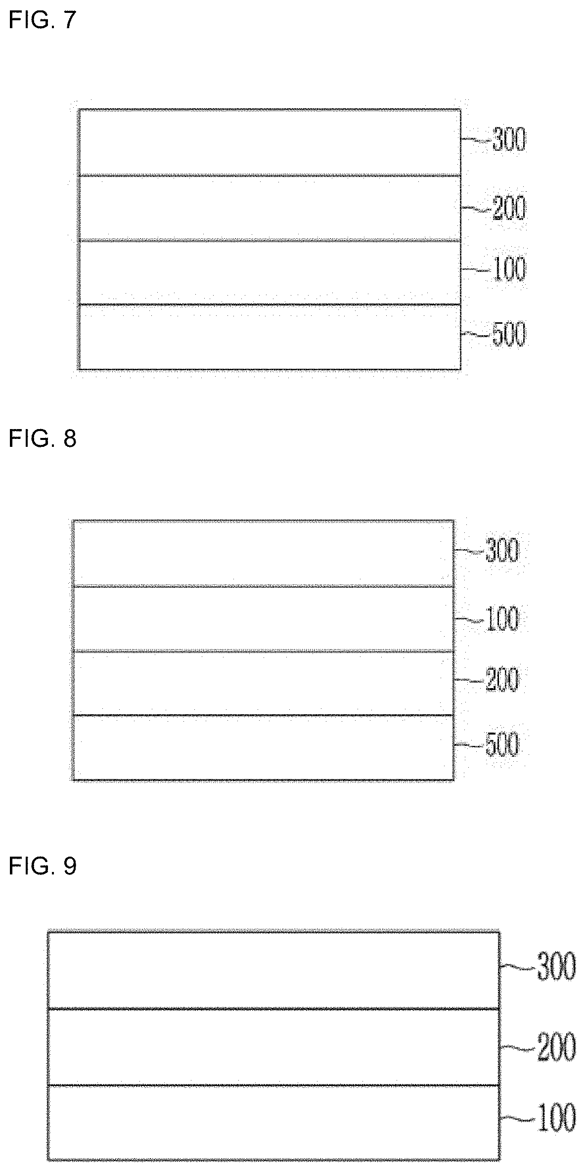
Disclosed are a laminated film including a light transmitting substrate; a hard coating layer; and an optical enhancement layer disposed between the light transmitting substrate and the hard coating layer or at a position facing the hard coating layer with the light transmitting substrate therebetween, wherein the light transmitting substrate includes a polyimide, a poly(amide-imide) copolymer, or a combination thereof, and the optical enhancement layer includes a copolymer comprising a polyimide, and a display device including the laminated film.

Description

CROSS-REFERENCE TO RELATED APPLICATION[0001]This application claims priority to and the benefit of Korean Patent Application No. 10-2018-0120054 filed in the Korean Intellectual Property Office on Oct. 8, 2018, and all the benefits accruing therefrom under 35 U.S.C. § 119, the content of which in its entirety is herein incorporated by reference.BACKGROUND1. Field[0002]A laminated film and a display device including the laminated film are disclosed.2. Description of the Related Art[0003]Portable display devices such as a smart phone or a tablet PC have been actively researched according to the high performance and popularization thereof. For example, lightweight, flexible (i.e., bendable or foldable) and portable display devices have been studied and developed to be commercialized. The portable display device of a liquid crystal display or the like includes a protective window for protecting a display module such as a liquid crystal layer. Currently, most portable display devices inc...

Claims


Application Information

Patent Timeline
Patent Type & Authority Applications(United States)
IPC IPC(8): B32B27/08B32B27/28B32B27/34B32B27/40
CPCB32B27/34B32B27/283B32B2255/26B32B27/08B32B27/40B32B27/281B32B2457/20B32B2307/412B32B2250/03B32B2255/10B32B2307/418C08J7/042G02B1/10G02B1/14G02B1/04C08J2379/08C08J2479/08C08J2483/04B32B1/00B32B7/023
Inventor JEON, HYUNJEONGJO, A RACHAE, JUNGHASONG, SUN JINJEONG, BOREUM
Owner SAMSUNG ELECTRONICS CO LTD
Learn More