Fuel Cell Arrangement

a fuel cell and arrangement technology, applied in the direction of electrolysis components, electrolysis processes, electrochemical generators, etc., can solve the problems of inability to accurately position the reference electrode, the exact position of the reference electrode on the z-axis is not known, and the unsuitable positioning of the reference electrode is not readily apparent, etc., to achieve the effect of sufficient accuracy

Active Publication Date: 2020-05-14
FORSCHUNGSZENTRUM JULICH GMBH
View PDF0 Cites 0 Cited by
  • Summary
  • Abstract
  • Description
  • Claims
  • Application Information

AI Technical Summary

Benefits of technology

[0018]Within the scope of the present invention, it was found, supported by numerical simulations for a polymer electrolyte membrane fuel cell (PEMFC) comprising a concentric small anode and a concentric large-surface-area (endless) cathode, that a novel arrangement overcomes the existing disadvantages of the prior art, based on, and in a continuation of, the arrangement of a reference electrode in a fuel cell as proposed in A. A. Kulikovsky and P. Berg (DE 102015001572.9). For this purpose, a fuel cell arrangement is proposed, in which it is possible to position a reference electrode at a considerably smaller distance than before from a counter electrode, and in particular an anode, and it is nonetheless possible to ascertain the overvoltage of the counter electrode, and in particular of a cathode, with sufficient accuracy. Moreover, this novel arrangement of the fuel cell regularly has electrode surface areas that are able to ensure sufficient electrochemical conversion.
[0027]Compared to the previously described straight edges of a counter electrode according to FIG. 3, the convexly curved region of the counter electrode having a radius of curvature Ra has the advantage that the minimum distance Lgap, at which the reference electrode is disposed from the counter electrode, is considerably smaller than the corresponding distance Lgap in the arrangement according to FIG. 4, while the overvoltage of the working electrode, and in particular of the cathode, can nonetheless be ascertained with sufficient accuracy. This is of crucial importance, in particular with small fuel cells.
[0028]The reference electrode can advantageously be designed to be very small with the arrangement according to the invention. In this way, it is possible to ensure that the tip of the convexly curved region of the counter anode is the closest region of the counter electrode. If this were not the case, the membrane potential could be impaired at the location of the reference electrode by contributions from remote regions of the anode.
[0030]In this arrangement of the counter electrode, the distance Lgap can be selected to be significantly smaller, which advantageously results in a much more compact design comprising the reference electrode. Nonetheless, such an arrangement advantageously makes it possible that the potential measured at the reference cell corresponds with sufficient accuracy to the overvoltage of the cathode.

Problems solved by technology

However, it has been found that suitable positioning of the reference electrode is not readily apparent.
In the implementation for positioning a reference electrode in a fuel cell according to FIG. 1, however, two essential problems occur.
A further problem, which occurs even in electrochemical cells in which the edges of the working electrodes are precisely aligned (δ=0), is that, even though the value of the potential Φ measured by the reference electrode corresponds to a point on the z-axis between the working electrodes, the exact position of this point on the z-axis is not known.
It is therefore not possible, in such a case, to unambiguously evaluate and interpret the measured DC voltage signal of the reference electrode.

Method used


Image

  • Fuel Cell Arrangement
  • Fuel Cell Arrangement
  • Fuel Cell Arrangement

Examples


Embodiment Construction

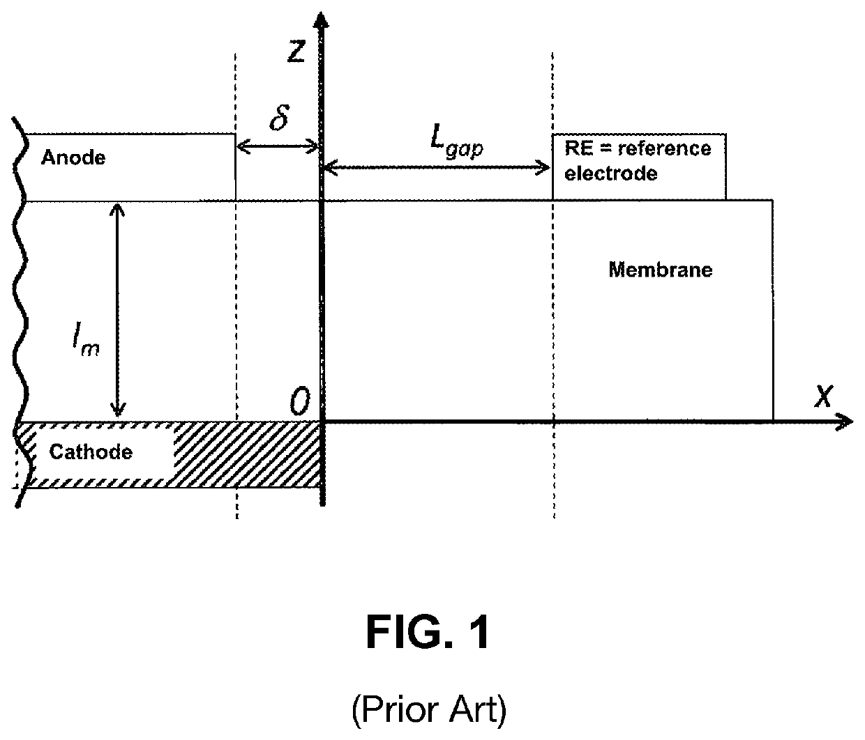
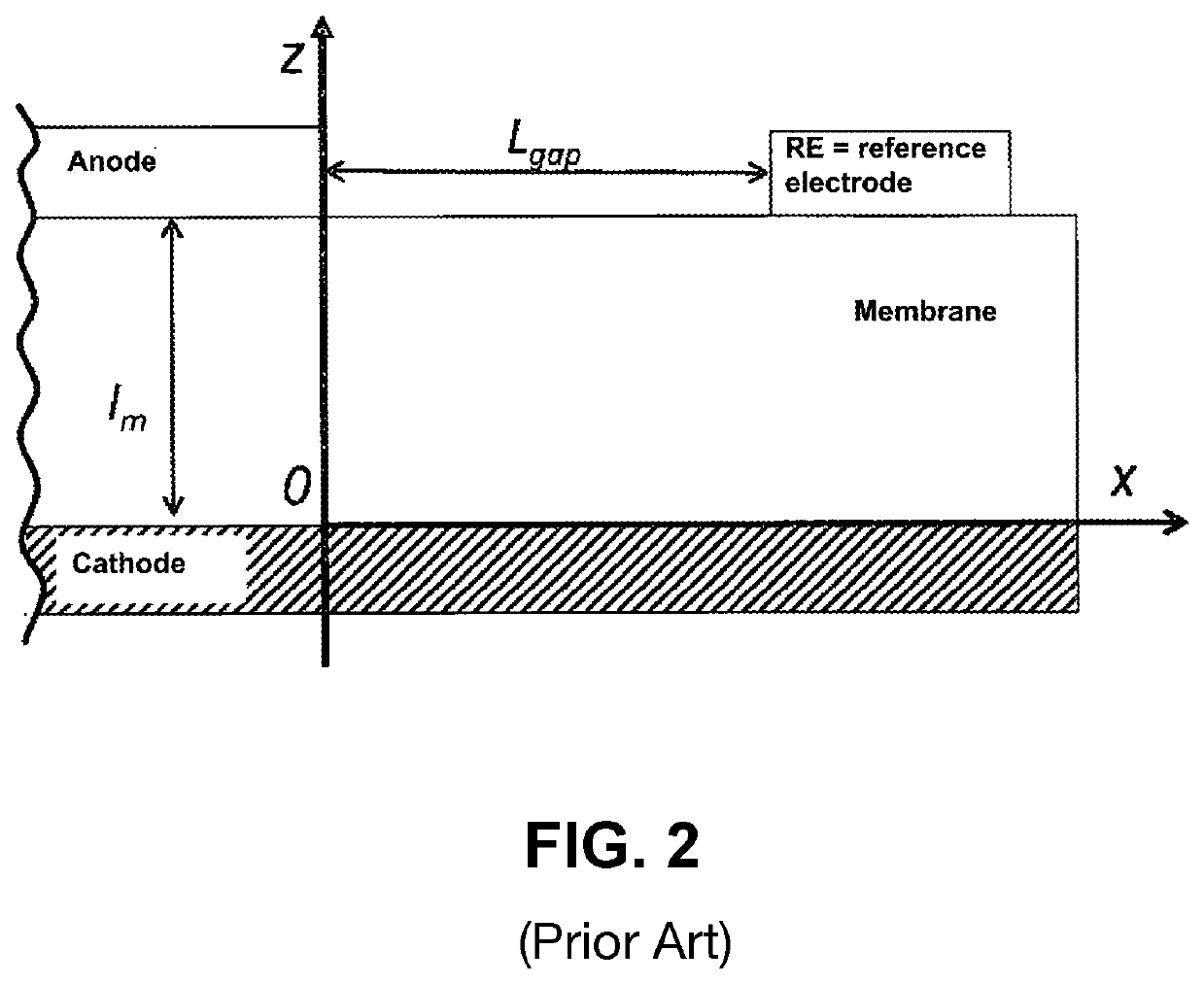
[0044]Hereafter, the fuel cell model and fundamental equations will be described, which serve as the basis for the numerical calculation for the fuel cell design according to the invention.

[0045]The following symbols are used:[0046]˜ denotes non-dimensional variables[0047]b Tafel slope of the half cell for the anodic or cathodic reaction (V)[0048]Eeq equilibrium potential of a half cell (V)[0049]F Faraday constant[0050]J average current density in the working area (A cm−2)[0051]ja local proton current density on the anode side (A cm−2)[0052]jc local proton current density on the cathode side (A cm−2)[0053]jhy hydrogen exchange current density (A cm−2)[0054]jhy0 hydrogen exchange current density in the working area (A cm−2)[0055]jox oxygen exchange current density (A cm−2)[0056]jox0 oxygen exchange current density in the working area (A cm−2)[0057]Lgap minimum distance between the edge of the counter electrode and the edge of the reference electrode[0058]Ll,x distance between the str...


PUM

PropertyMeasurementUnit
radius Raaaaaaaaaaa
radius Raaaaaaaaaaa
local radius Raaaaaaaaaaa

Abstract

A fuel cell arrangement for carrying out a method for ascertaining the overvoltage of a working electrode in a fuel cell, in which the potential of a reference electrode compared to the grounded counter electrode is measured. For the measurement, a fuel cell comprising a polymer electrolyte membrane is used, in which the counter electrode comprises a lateral edge having at least one convexly curved region, and the electrolyte membrane surface, adjoining the counter electrode, comprises an electrode-free region in which the reference electrode is disposed on the electrolyte membrane surface. In contrast, the working electrode is continuous, which is to say has a large surface. The minimum distance Lgap between the reference electrode and the edge of the counter electrode Lgap=3×Ll,r with (a) and (b), where m=ionic conductivity of the electrolyte membrane (Ω−1 cm −1), box=Tafel slope of the half cell for the electrochemical reaction of the working electrode, lm=membrane layer thickness (cm) and jox0=exchange current density of the catalyst of the working electrode per unit of electrode surface in (A cm−2). This arrangement can advantageously be used to ensure that the potential measured at the hydrogen-fed reference electrode corresponds to the overvoltage of the working electrode with sufficient accuracy. The method can be applied to polymer electrolyte membrane fuel cells (PEMFC), to direct methanol fuel cells (DMFC) or to high-temperature fuel cells (SOFC).

Description

[0001]The invention relates to a novel fuel cell design, in particular for a polymer electrolyte membrane fuel cell (PEMFC), for ascertaining overvoltages.BACKGROUND OF THE INVENTION[0002]In an electrochemical cell, the electrochemical reactions at the involved electrodes are decisively influenced by the half-cell overvoltages. These overvoltages include both contributions from the activation and from transport losses of the corresponding half cells. It is therefore considered to be a primary objective to minimize these contributions within the scope of a novel cell concept. One of the most common previous methods for measuring half-cell overvoltages is a method using a reference electrode (RE).[0003]A reference electrode is always aimed at measuring the potential Φ of the electrolyte membrane at an arbitrary point between two electrodes. Having knowledge of this potential makes it possible, in principle, to separate the cathode overvoltage and the anode overvoltage. However, it has...

Claims


Application Information

Patent Timeline
Patent Type & Authority Applications(United States)
IPC IPC(8): H01M8/04537H01M8/1006H01M8/12H01M8/1018H01M8/1011C25B11/00C25B1/02
CPCH01M8/04544H01M8/1006H01M8/1018C25B1/02H01M2008/1095Y02E60/523H01M2008/1293C25B11/00H01M8/1011H01M8/12H01M8/04552Y02E60/50
Inventor KULIKOVSKY, ANDREI
Owner FORSCHUNGSZENTRUM JULICH GMBH
Why Eureka
Try Eureka