
Heat treatment apparatus of mea for fuel cell

a technology of heat treatment apparatus and fuel cell, which is applied in the direction of chemistry apparatus and processes, electrolyte generators, other domestic articles, etc., can solve the problems of insufficient interfacial bond strength between the electrolyte membrane and the electrolyte membrane, and the performance and durability of the membrane-electrode assembly may be reduced, so as to increase the performance and durability of the membrane-electrode assembly, and ensure mass productivity. the effect of bonding strength

Active Publication Date: 2020-05-14
HYUNDAI MOTOR CO LTD +1
View PDF0 Cites 3 Cited by
  • Summary
  • Abstract
  • Description
  • Claims
  • Application Information

AI Technical Summary

Benefits of technology

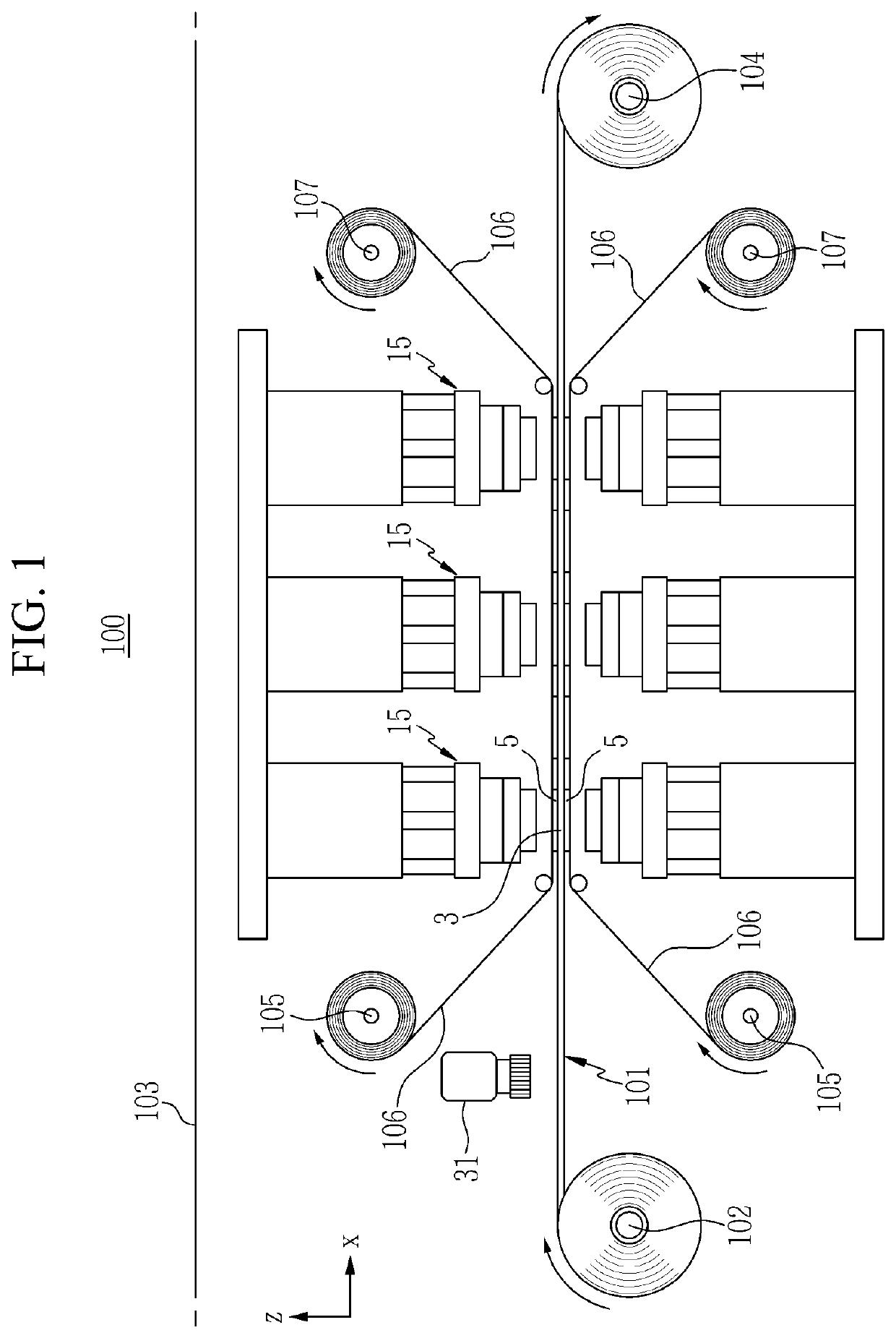
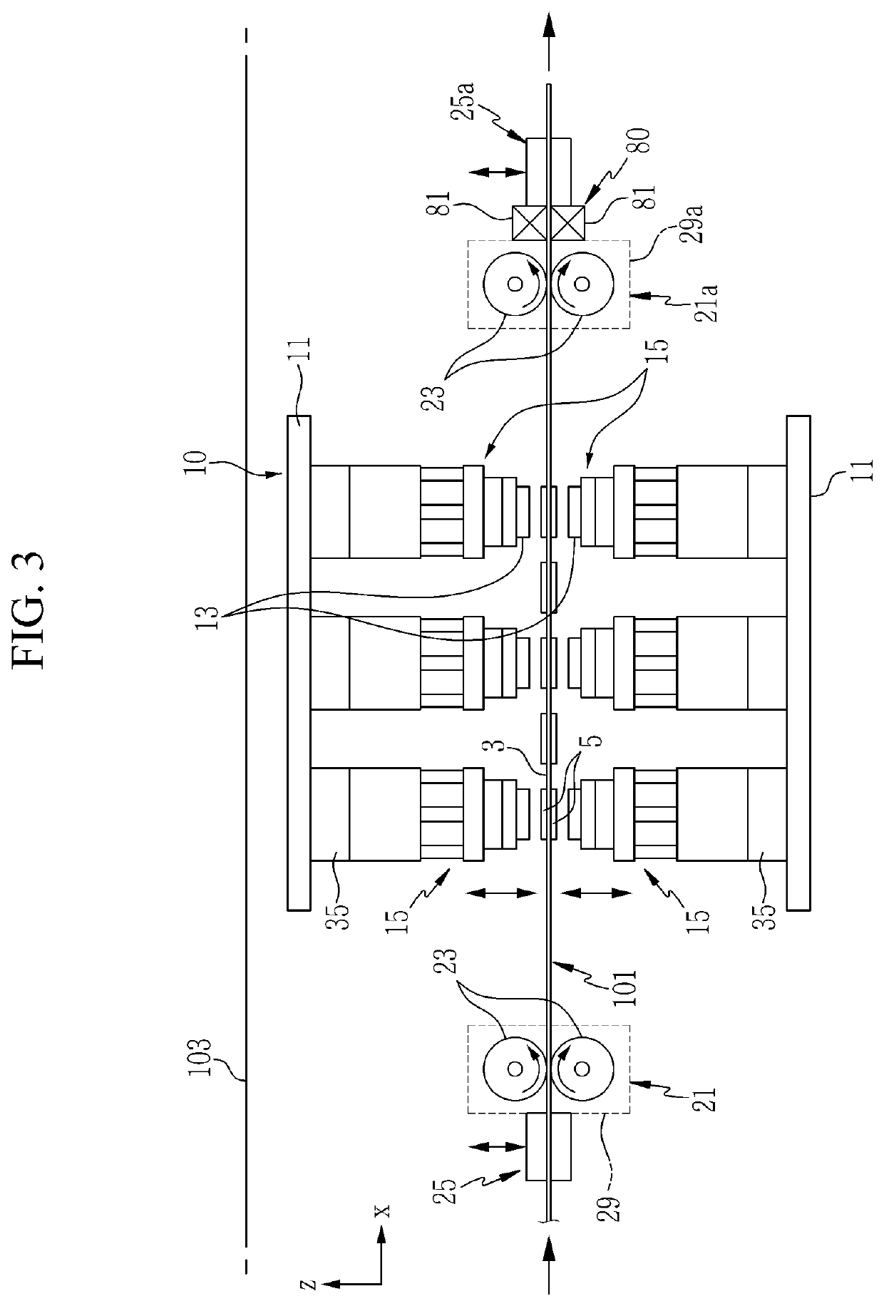
The present invention provides a heat treatment apparatus for a membrane-electrode assembly for a fuel cell that prevents shrinkage and serpentine deformation of the membrane-electrode assembly sheet during a hot press process. This improves the interface bonding strength between the electrolyte membrane and the electrode catalyst layer, ensuring mass productivity and durability of the membrane-electrode assembly. The hot-shrinkage and serpentine deformation may be prevented by applying tension to the membrane-electrode assembly sheet through the gripper module and cooling air to prevent wrinkle deformation of the sub-gasket. The present invention secures the lamination alignment of the fuel cell during the fuel cell stacking process and improves the yield of the fuel cell stack.

Problems solved by technology

However, the interfacial bond strength between the electrolyte membrane and the electrolyte membrane is insufficient.
However, the performance and durability of the membrane-electrode assembly may be reduced if elimination occurs at the interface between the electrode catalyst layer and the electrolyte membrane due to the lack of interface bonding strength between the electrode catalyst layer and the electrolyte membrane.

Method used


Image

  • Heat treatment apparatus of mea for fuel cell
  • Heat treatment apparatus of mea for fuel cell
  • Heat treatment apparatus of mea for fuel cell

Examples


Embodiment Construction

[0074]It is understood that the term “vehicle” or “vehicular” or other similar term as used herein is inclusive of motor vehicles in general such as passenger automobiles including sports utility vehicles (SUV), buses, trucks, various commercial vehicles, watercraft including a variety of boats and ships, aircraft, and the like, and includes hybrid vehicles, electric vehicles, plug-in hybrid electric vehicles, hydrogen-powered vehicles and other alternative fuel vehicles (e.g. fuels derived from resources other than petroleum). As referred to herein, a hybrid vehicle is a vehicle that has two or more sources of power, for example both gasoline-powered and electric-powered vehicles.

[0075]Although exemplary embodiment is described as using a plurality of units to perform the exemplary process, it is understood that the exemplary processes may also be performed by one or plurality of modules. Additionally, it is understood that the term controller / control unit refers to a hardware devi...


PUM

PropertyMeasurementUnit
actuating forceaaaaaaaaaa
temperatureaaaaaaaaaa
pressureaaaaaaaaaa

Abstract

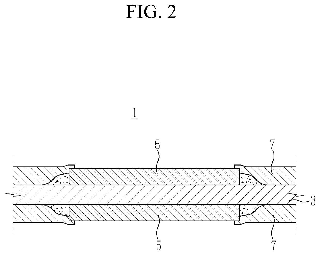
A heat treatment apparatus for a fuel cell membrane-electrode assembly is provided. The heat treatment apparatus includes a hot press installed on upper and lower sides of feeding path to move in the vertical direction on a frame and which presses the electrode catalyst layers on upper and lower surfaces of the membrane-electrode assembly sheet. A plurality of gripper modules are installed at set intervals in a base member along a feeding direction of the membrane-electrode assembly sheet, and selectively grip both side edges of the membrane-electrode assembly sheet. A driving unit reciprocally moves the base member in a direction perpendicular to the feeding direction of the membrane-electrode assembly sheet and in the feeding direction of the membrane-electrode assembly sheet.

Description

CROSS-REFERENCE TO RELATED APPLICATION[0001]This application claims priority to and the benefit of Korean Patent Application No. 10-2018-0137413 filed on Nov. 9, 2018, the entire contents of which are incorporated herein by reference.BACKGROUND(a) Field of the Invention[0002]The present invention relates to a system for manufacturing membrane-electrode assemblies (MEAs) for fuel cells, and more particularly, to a heat treatment apparatus of a membrane-electrode assembly for a fuel cell for heat treatment of a membrane-electrode assembly.(b) Description of the Related Art[0003]As is known in the field, a fuel cell produces electricity by reaction, which is an electrochemical reaction of hydrogen and oxygen. Such a fuel cell is capable of continuously generating electricity by supplying chemical reactants from the outside without a separate charging process. The fuel cell may be constructed by disposing a separating plate or a bipolar plate on both sides of a membrane-electrode assemb...

Claims


Application Information

Patent Timeline
Patent Type & Authority Applications(United States)
IPC IPC(8): H01M8/1086H01M8/1006H01M8/04701
CPCH01M8/04731H01M8/1006H01M8/109H01M8/1004H01M2008/1095H01M8/0273Y02E60/50B32B37/10B32B37/06B32B5/02B32B2457/18
Inventor HONG, YOOSUKJEONG, SUNG HOON
Owner HYUNDAI MOTOR CO LTD
Learn More