System for the storage of fuel gases

a fuel gas and gas storage technology, applied in the direction of electrochemical generators, container discharging methods, vessel construction details, etc., can solve the problems of not being the most efficient, not being able to achieve the most efficient, etc., to achieve optimal safety

Active Publication Date: 2020-05-21
H2 ENERGY LLC
View PDF4 Cites 2 Cited by
  • Summary
  • Abstract
  • Description
  • Claims
  • Application Information

AI Technical Summary

Benefits of technology

[0012]The object of the present invention is to overcome the drawbacks of the prior art. More precisely, it is an object of the present invention to provide quick refill of a multi-capillary tank with highly pressurized gas and controlled release of the gas from the multi-capillary tank to t

Problems solved by technology

One of the problems faced by hydrogen energy is the safe storage and regulated supply of hydrogen fuel to the fuel cell.
All these methods have significant limitations on the gravimetric and volumetric content of hydrogen in the fuel storage and supply system (Gupta R., Basile A., Veziroglu T. N. (ed.
Such an approach is not seen as the most efficient, it is too complicated to regulate, and it requires energy to heat the layers (plugs) that can lead to additional glass tension due to the difference in the coefficients of volumetric expansion of glass and the material of the layers (plugs).
Another disadvantage of such solutions is that they do

Method used


Image

  • System for the storage of fuel gases
  • System for the storage of fuel gases
  • System for the storage of fuel gases

Examples


first embodiment

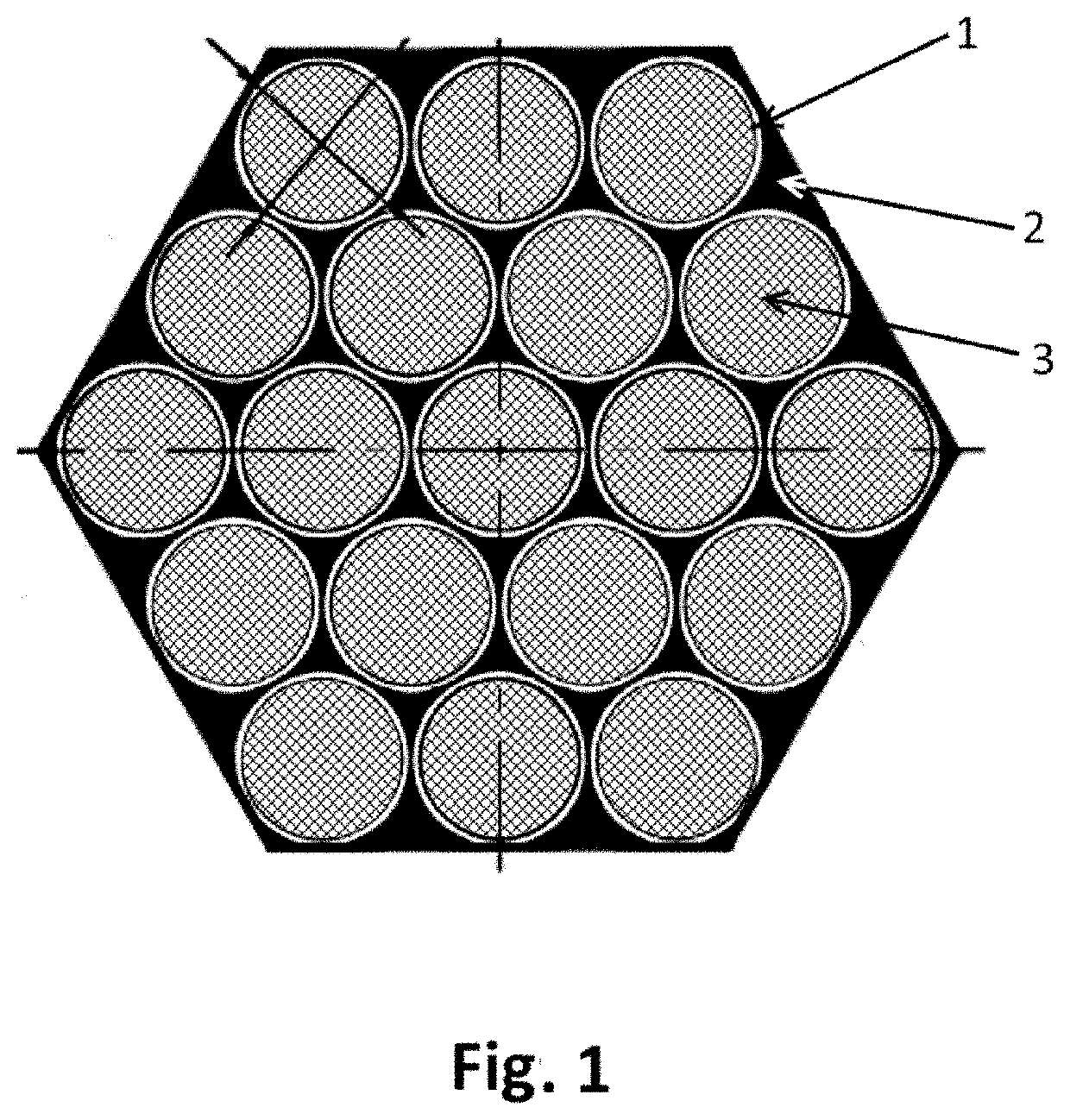
[0048]FIG. 1 shows the schematic cross section of the first embodiment multi-capillary unit for the storage and transportation of hydrogen to the fuel cell. The structure consists of a set of identical cylindrical thin-wall glass micro-capillaries (1), tightly packed into a hexagonal or other matrix, closed from the ends with metal plugs (3) with sufficiently low melting point of the metal, having sufficiently good adhesion to glass and chemical resistance to hydrogen, such as indium-tin alloy In50Sn. After cooling the melt inside the capillaries below the melting point, a solid metal plug (3) is formed. The length of the plug L is determined from the condition of exceeding the adhesive force of the plug with the inner surface of the capillary above the force that pushes the plug out if the capillary is filled with gas with pressure P.

[0049]According to calculations, the length of the tube L must satisfy the condition:

L>Pr / (2k)

Here r is the internal diameter of the capillary, k is t...

second embodiment

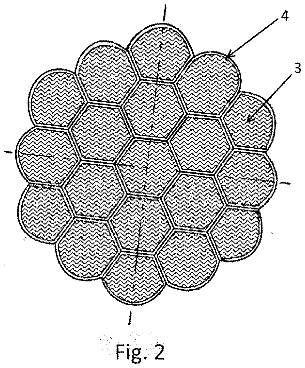
[0054]The second embodiment is shown schematically in FIG. 2. In this case internal micro-capillaries (1) have the shape of hexagonal prisms with common faces, forming a honeycomb structure in cross section, and the outer micro-capillaries have a special shape, where instead of flat faces they have cylindrical faces (4) on the outer surface and therefore do not experience bending deformation when the structure is under the internal gas pressure that may be critical for the glass strength. The corresponding shape of the outer capillaries can be obtained, for example, from flat edges, if the multi-capillary structure of fully hexagonal prisms is first soldered at both ends and then heated. Arising internal pressure due to the air expansion inside the capillaries deforms the faces of the outer capillaries as necessary, if the viscosity of glass is low enough. To create the plugs (3), the initially open end of the micro-capillaries is immersed in the melted metal alloy and some rarefact...


PUM

PropertyMeasurementUnit
Fractionaaaaaaaaaa
Fractionaaaaaaaaaa
Fractionaaaaaaaaaa

Abstract

Disclosed is a gas storage, preferably of hydrogen, and is in the form of a multi-capillary structure. The multi-capillary structure has a constant section over a certain length, which section then reduces sharply, down to a value at which the multi-capillaries become sufficiently flexible. The area of flexibility of the multi-capillaries has a length sufficient for the transportation of hydrogen to a fuel element. In this way, a flexible multi-capillary gas pipeline is created, which pipeline is integrated with a volume of stored hydrogen, the function of which pipeline is to supply hydrogen to the fuel element. The technical result consists of the provision of rapid priming of a micro-capillary vessel with high pressure gas and the regulated release of the gas from the vessel into a collector, where a moderate pressure (<1 MPa), required for operation of the fuel element, is maintained.

Description

CROSS-REFERENCE[0001]The present application is a Continuation of International Application No. PCT / RU2018 / 000495, filed on Jul. 25, 2018, entitled “SYSTEM FOR THE STORAGE OF FUEL GASES”, which claims priority to Russian Patent Application No. 2017127195, filed on Jul. 28, 2017, the entirety of which is incorporated herein by reference.FIELD OF THE INVENTION[0002]The invention relates to the field of storage of gases under high pressure. More precisely, the invention relates to compact and light storage of gases such as hydrogen and methane. The invention can find application in the field of engines, in particularly automotive, in which catalytic reactions of fuel gases with oxygen in fuel cells are used to generate electricity.BACKGROUND[0003]Currently, the most common sources of electrical energy for mobile electronics and unmanned aerial vehicles are nickel-polymer or lithium-polymer batteries. The best lithium-polymer batteries have a specific energy consumption of about 200 Wh ...

Claims


Application Information

Patent Timeline
IPC IPC(8): F17C1/00
CPCF17C2201/0166F17C2203/0634F17C2221/012F17C2270/0184F17C1/00F17C11/00Y02E60/32F17C1/16F17C2201/056F17C2203/066F17C2205/0311F17C2209/234F17C2223/0123F17C2223/036F17C2250/043F17C2270/0168Y02P90/45Y02E60/50F17C13/12
Inventor ZHEVAGO, NIKOLAJ KONSTANTINOVICH
Owner H2 ENERGY LLC
Why Eureka
Try Eureka