Color mixing in laser-based light source

a laser-based light source and color mixing technology, applied in the field of lighting devices, can solve the problems of inability to apply dichroic filters at all, relative high cost, etc., and achieve the effect of improving efficiency and improving spectral distribution

Active Publication Date: 2020-07-02
SIGNIFY HLDG BV
View PDF0 Cites 1 Cited by
  • Summary
  • Abstract
  • Description
  • Claims
  • Application Information

AI Technical Summary

Benefits of technology

[0072]For further improving efficiency and/or for improving the spectral distribution several optical elements may be included like mirrors, optical filters, additional optics, etc. In specific embodiments, the lighting device may have a mirror configured at the first face configured to reflect light back into the elongated light transmissive body, and/or may have one or more of an optical filter, a (wavelength selective) mirror, a refle

Problems solved by technology

In such solution, dichroic filters may be used but these require collimated light and relatively large and complex optics, bringing relatively high costs.
In s

Method used


Image

  • Color mixing in laser-based light source
  • Color mixing in laser-based light source
  • Color mixing in laser-based light source

Examples


Embodiment Construction

[0099]A light emitting device according to the invention may be used in applications including but not being limited to a lamp, a light module, a luminaire, a spot light, a flash light, a projector, a (digital) projection device, automotive lighting such as e.g. a headlight or a taillight of a motor vehicle, arena lighting, theater lighting and architectural lighting.

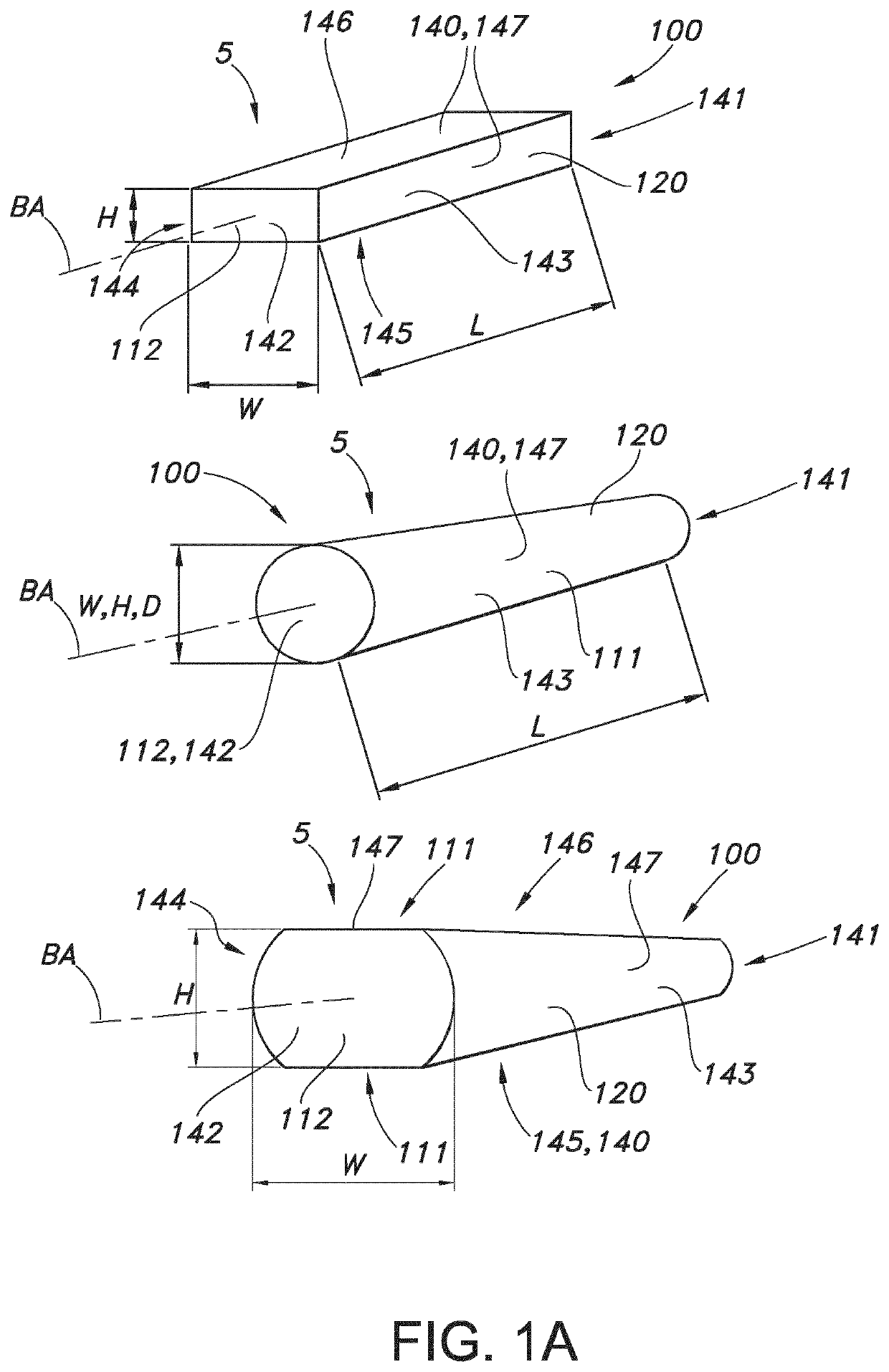
[0100]Light sources which are part of the embodiments according to the invention as set forth below, may be adapted for, in operation, emitting light with a first spectral distribution. This light is subsequently coupled into a light guide or waveguide; here the light transmissive body. The light guide or waveguide may convert the light of the first spectral distribution to another spectral distribution and guides the light to an exit surface.

[0101]FIG. 1a schematically depicts some embodiments of possible bodies, such as ceramic bodies or crystals as waveguides. The faces are indicated with references 141-146. The firs...


PUM


Abstract

The invention provides a lighting device (1) lighting device (10) comprising: (I) a first light source (110) configured to provide first light source light (101); (II) a luminescent material (200) configured to convert at least part of the first light source light (101) into luminescent material light (201); (III) a beam shaping optical element (300) having a light entrance side (341) and a light exit side (342), and a wall (347) bridging a distance between the light entrance side (341) and the light exit side (342), wherein at least part of the wall (347) is reflective for the luminescent material light (201), wherein the beam shaping optical element (300) is configured to receive at least part of the luminescent material light (201) at the light entrance side (341) and to provide beam shaped luminescent material light (201) at the light exit side (342); (IV) an elongated light transmissive body (100) having a first face (141) and a second face (142) defining a length (L) of the light transmissive body (100), and having one or more side faces (147) bridging the length (L) between the first face (141) and the second face (142), the light transmissive body (100) comprising a radiation input face (111) and a first radiation exit window (112), wherein the first face (141) comprises the radiation input face (111) and wherein the second face (142) comprises the first radiation exit window (112), wherein the radiation input face (111) is configured to receive at least part of the beam shaped light luminescent material light (201); (V) a second light source (120) configured to provide second light source light (121); wherein the elongated light transmissive body (100) is configured to receive at least part of the second light source light (121) via one or more of (i) incoupling of the second light source light (121) via the wall (347) of the beam shaping optical element (300), (ii) incoupling of the second light source light (121) via part of the first face (141) of the elongated light transmissive body (100), and (iii) incoupling of the second light source light (121) via part of the of the one or more side faces (147) of the elongated light transmissive body (100).

Description

FIELD OF THE INVENTION[0001]The invention relates to a lighting device, such as for use in a projector or for use in spot lighting or stage lighting.BACKGROUND OF THE INVENTION[0002]Light combining devices are known in the art. US 2014 / 0240677, for instance, describes a light source comprising a light combining device for guiding incident light from a first light emitting source and incident light from a second light emitting source with different incident directions to combine two paths of incident light into one path of emission light emitted from a first optical path. The light combining device comprises a guide part, for guiding light from the second light emitting source to converge into the first optical path, and hindering a part of light from the first light emitting source from entering the first optical path, the luminous flux of the hindered part of the light being less than the luminous flux of light from the first light emitting source entering the first optical path. T...

Claims


Application Information

Patent Timeline
IPC IPC(8): G02B27/09G02B19/00G03B21/20
CPCG03B21/208G02B27/0916G02B19/0052G03B21/204G02B27/0994G02B6/0003G02B6/0068G02B19/0028F21S41/14G03B21/2013F21S43/14F21S43/237F21S43/243F21S43/249
Inventor CORNELISSEN, HUGO JOHANVDOVIN, OLEXANDR VALENTYNOVYCHPATENT, EVGENI ARKAD'EVICHBENOY, DANIEL ANTON
Owner SIGNIFY HLDG BV
Why Eureka
Try Eureka