Magneto-optical trap method and apparatus

a magneto-optical and trapping technology, applied in the field of narrowline magneto-optical trapping apparatus, can solve the problems of large improvement space, large system size, and clocked system, and achieve the effect of shortening the time required for cooling/trapping, improving the trapping force and the atomic density

Pending Publication Date: 2020-08-27
NIPPON TELEGRAPH & TELEPHONE CORP +1
View PDF0 Cites 3 Cited by
  • Summary
  • Abstract
  • Description
  • Claims
  • Application Information

AI Technical Summary

Benefits of technology

[0014]The present invention has been made to solve the above problems, and has as its object to provide a magneto-optical trap method and a magneto-optical trap apparatus capable of improving the trapping force and the atomic density of a narrow-line magneto-optical trap, thereby shortening the time required for cooling / trapping of atoms.

Problems solved by technology

When taking a laser system as an example, however, it is necessary to simultaneously control about 10 lasers, so the size of the system tends to increase.
Since clock systems are complicated as described above, there may still be much room for improvement.
There are some problems related to the frequency stability of the optical lattice clock.
This may also be a cause that decreases the atomic density.

Method used


Image

  • Magneto-optical trap method and apparatus
  • Magneto-optical trap method and apparatus
  • Magneto-optical trap method and apparatus

Examples


Embodiment Construction

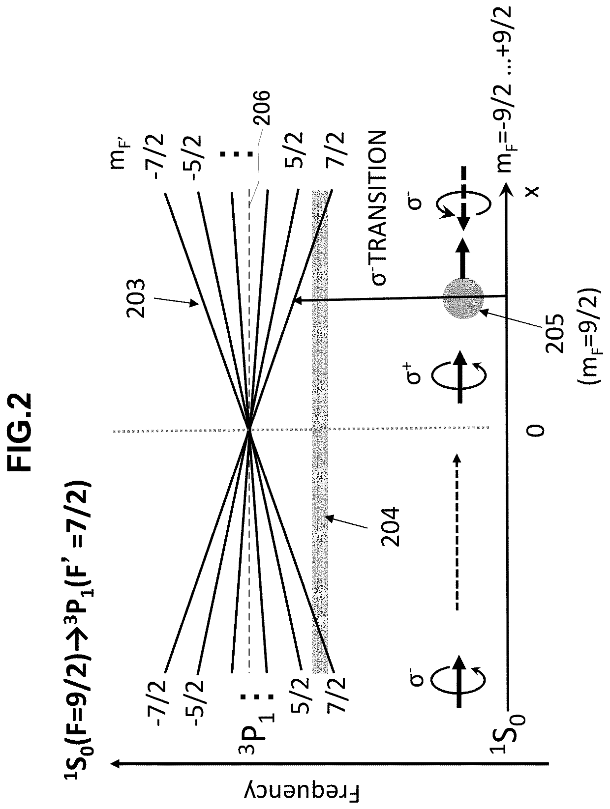
[0028]Embodiments of the present invention will be explained below. In the following embodiments, a narrow-line dual-operation magneto-optical trap (to be referred to as MOT hereinafter) will be proposed for the purposes of shortening the deadtime and increasing the atomic density. A related narrow-line MOT that traps only an atom of mFF>0 as well. This makes it possible to efficiently apply the trapping force on all magnetic quantum numbers mF. Consequently, the atomic density increases, and the efficiency of transition of the number of atoms from the narrow-line MOT to an optical lattice potential expectably improves.

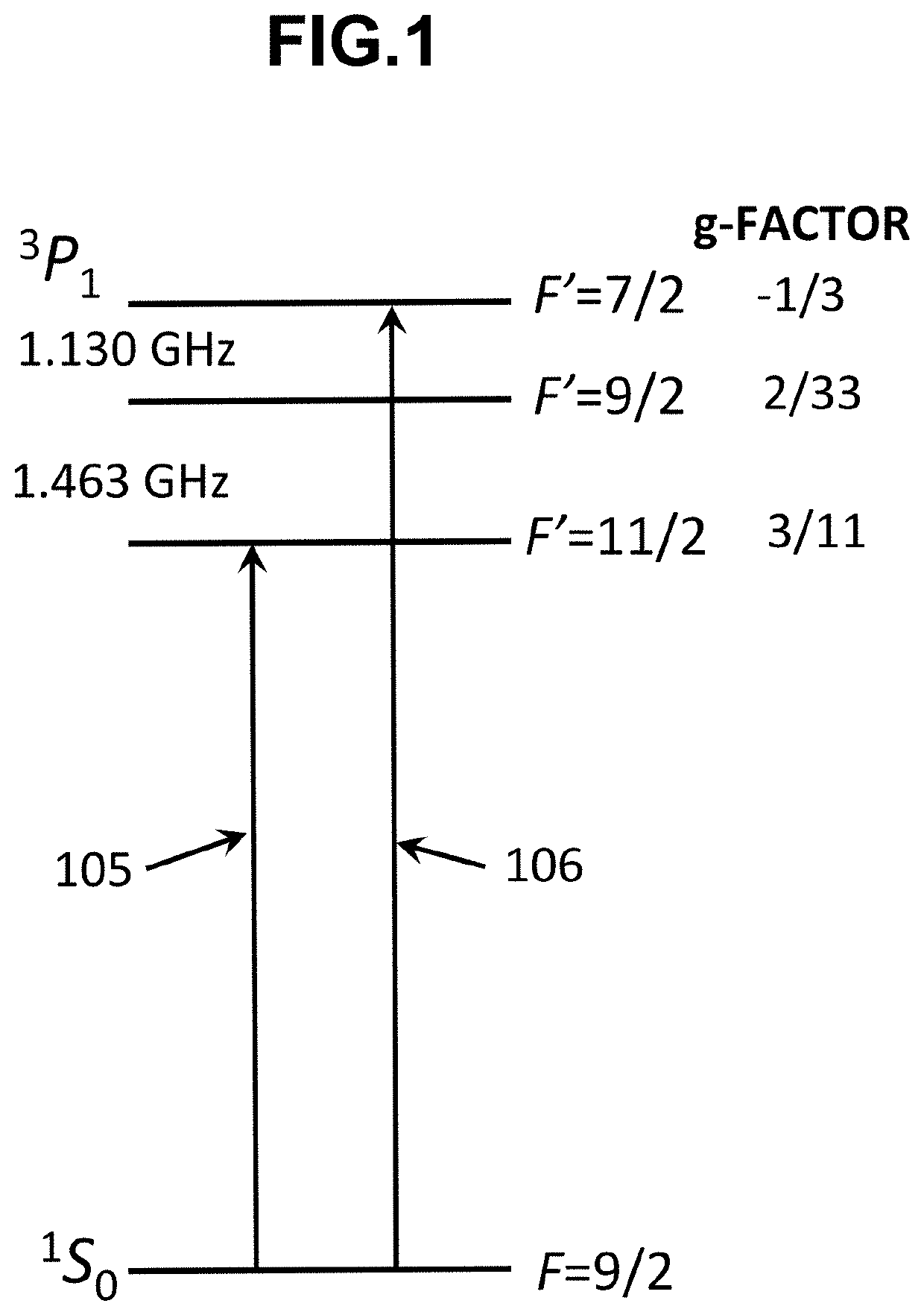
[0029]A narrow-line dual-operation MOT will be explained below. As shown in FIG. 1, this narrow-line dual-operation MOT uses a trapping beam 105 (to be referred to as an F′=11 / 2 laser hereinafter) having a frequency detuned to the negative side with respect to the resonance frequency when an atom transits from 1S0 (F=9 / 2) to 3P1 (F′=11 / 2). In addition, a trapping beam...


PUM


Abstract

A magneto-optical trap apparatus includes a vacuum vessel for encapsulating an atom to be trapped, an anti-Helmholtz coil for applying a magnetic field to an inside of the vacuum vessel, a laser device for generating a laser beam, and an irradiation device for irradiating the generated laser beam from a plurality of directions. The laser beam includes a first laser beam detuned from a first resonance frequency when the atom transits from a total angular momentum quantum number F in a ground state to a total angular momentum quantum number F′=F+1 in an excited state, and a second laser beam detuned from a second resonance frequency when the atom transits from the total angular momentum quantum number F in the ground state to a total angular momentum quantum number F′=F−1 in the excited state, among transitions from J=0 in a ground state to J′=1 in an excited state.

Description

BACKGROUND OF THE INVENTION[0001]The present invention relates to an improvement of the atomic density of a narrow-line magneto-optical trap apparatus.[0002]Recently, the research of an optical atomic clock such as an optical lattice clock and an ion clock using an optical frequency has extensively been made, and the clock accuracy has reached the order of 10−18 (literature 1: Ichiro Ushijima, Masao Takamoto, Manoj Das, Takuya Ohkubo, and Hidetoshi Katori, “Cryogenic optical lattice clocks”, Nature Photonics, VOL. 9, pp. 185-189, 2015). The abovementioned clock has already surpassed the accuracy of 133 cesium (Cs) atomic clock that is used to define the second at present by two orders of magnitude, and is nominated as a candidate for a next-generation time / frequency standard. An optical clock network constructed by connecting these high-accuracy atomic clocks on commercial optical fiber networks can be applicable to geodesy such as altitude mapping and communication (literature 2: F...

Claims


Application Information

Patent Timeline
Patent Type & Authority Applications(United States)
IPC IPC(8): H05H3/02G21K1/093
CPCG21K1/093H05H3/02G21K1/006G04F5/145
Inventor IMAI, HIROMITSUAKATSUKA, TOMOYOOGURI, KATSUYAISHIZAWA, ATSUSHIGOTOH, HIDEKIKATORI, HIDETOSHITAKAMOTO, MASAO
Owner NIPPON TELEGRAPH & TELEPHONE CORP
Why Eureka
Try Eureka