
Method for manufacturing a structure for forming a tridimensional monolithic integrated circuit

Active Publication Date: 2020-09-17
S O I TEC SILICON ON INSULATOR THECHNOLOGIES
View PDF0 Cites 0 Cited by
  • Summary
  • Abstract
  • Description
  • Claims
  • Application Information

AI Technical Summary

Benefits of technology

The patent describes a new layer made of a mixture of alloys called six-ge1-x. This layer has very good quality and high mobility of electric current carriers, which makes it ideal for making highly performance and low power integrated circuits. The layer is also very strong, with metal-metal bonding being significantly stronger than dielectric-dielectric bonding at temperatures not exceeding 400°C. Additionally, the metal-metal interface is resistant to attack by a specific solution used for etching a specific layer.

Problems solved by technology

However, such a transfer is at issue when the component is likely to be damaged when subjected to a temperature higher than 400° C.
Indeed, to date there is no method enabling a semiconductor layer with a good crystal quality to be transferred and involving only steps that can be implemented at a temperature lower than 400° C.
However, such a deposition made at a temperature lower than 400° C. results in obtaining a polycrystalline or amorphous layer, not having the required crystal quality for the subsequent formation of other electronic components.
However, this implantation generates defects in the transferred layer, which can only be cured to date by an annealing at a temperature higher than 500° C.
However, these techniques enable neither very thin layers to be formed nor a satisfactory bonding energy to be achieved if the temperatures used do not exceed 400° C.

Method used


Image

  • Method for manufacturing a structure for forming a tridimensional monolithic integrated circuit
  • Method for manufacturing a structure for forming a tridimensional monolithic integrated circuit
  • Method for manufacturing a structure for forming a tridimensional monolithic integrated circuit

Examples


Embodiment Construction

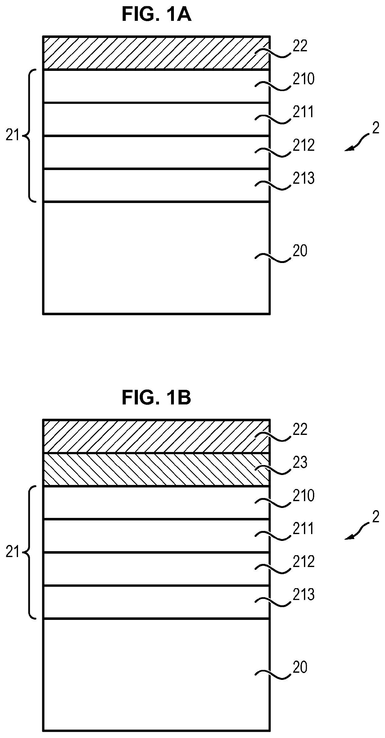
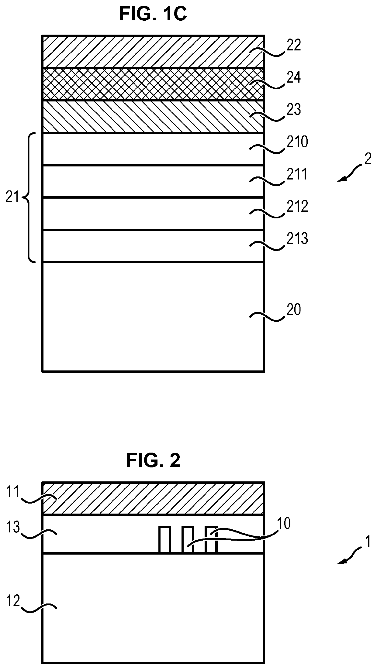
[0077]FIGS. 1A to 1C illustrate various alternatives of the donor substrate.

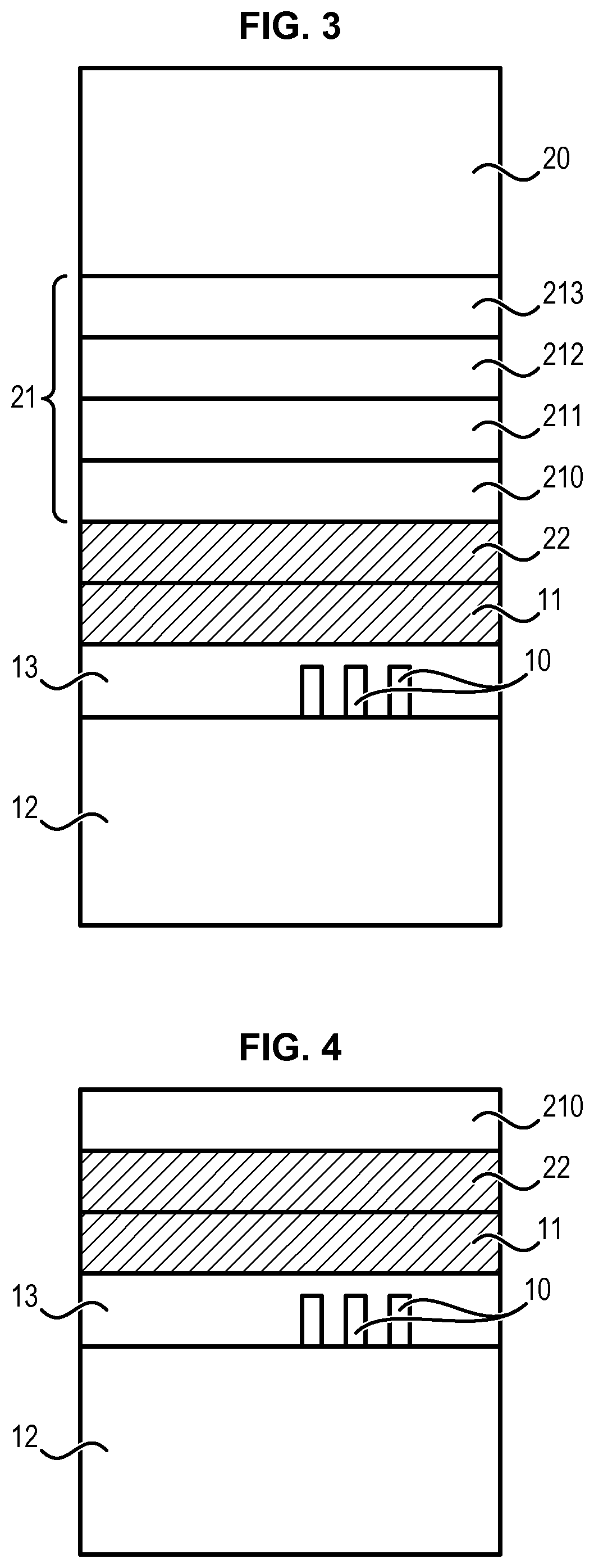
[0078]Generally, the donor substrate comprises successively:[0079]a base substrate 20,[0080]a stack 21 of a plurality of semiconductor epitaxial layers, among which a layer 210 of SixGe1-x, with 0≤x≤1, which is located at the surface of the stack that is opposite to the base substrate 20, the layer being intended to be transferred to another substrate to form the final structure,[0081]a bonding metal layer 22.

[0082]The base substrate 20 is of a semiconductor material, or a stack of different semiconductor materials. According to one particular embodiment, the base substrate is of bulk single crystal silicon.

[0083]In FIGS. 1A to 1C, the stack 21 is represented as four layers 213, 212, 211 and 210. However, those skilled in the art could vary the number of layers and their compositions without departing from the scope of the disclosure, as long as a layer underlying the layer 210 makes up an etching barrier la...


PUM


Abstract

A method for manufacturing a structure comprising a first substrate comprising at least one electronic component likely to be damaged by a temperature higher than 400° C. and a semiconductor layer extending on the first comprises:(a) providing a first bonding metal layer on the first substrate,(b) providing a second substrate comprising successively:a semiconductor base substrate,a stack of a plurality of semiconductor epitaxial layers, a layer of SixGe1-x, with 0≤x≤1 being located at the surface of said stack opposite to the base substrate, anda second bonding metal layer,(c) bonding the first substrate and the second substrate through the first and second bonding metal layers at a temperature lower than or equal to 400° C., and(d) removing a part of the second substrate so as to transfer the layer of SixGe1-x on the first substrate using a selective etching process.

Description

CROSS-REFERENCE TO RELATED APPLICATIONS[0001]This application is a national phase entry under 35 U.S.C. § 371 of International Patent Application PCT / EP2017 / 057717, filed Mar. 31, 2017, designating the United States of America and published in English as International Patent Publication WO 2017 / 167976 A1 on Oct. 5, 2017, which claims the benefit under Article 8 of the Patent Cooperation Treaty to French Patent Application Serial No. 1652768, filed Mar. 31, 2016.TECHNICAL FIELD[0002]The present application relates to a method for manufacturing a structure for forming a monolithic integrated circuit, as well as a structure and a substrate intended to be used for implementing the method.BACKGROUND[0003]Tridimensional (3D) monolithic integrated circuits are particularly promising in view of increasing the density and decreasing the size of electronic components, because they especially avoid misalignment problems of the components.[0004]The manufacture of such circuits involves transfer...

Claims


Application Information

Patent Timeline
IPC IPC(8): H01L29/161H01L23/00
CPCH01L2224/83894H01L29/161H01L24/83H01L21/187H01L21/30604H01L21/32115H01L21/768H01L25/50
Inventor FIGUET, CHRISTOPHEECARNOT, LUDOVICNGUYEN, BICH-YENSCHWARZENBACH, WALTERDELPRAT, DANIELRADU, IONUT
Owner S O I TEC SILICON ON INSULATOR THECHNOLOGIES
Learn More