
Circular polarization-type polarization diversity element, scanning element using same, and lidar

a technology of diversity element and polarization type, applied in the direction of polarizing element, instrument, measurement device, etc., can solve the problems of difficult mounting of lidar on top of the vehicle, unsuitable for mass production, unusable element operating on circular polarized light, etc., and achieve the effect of reducing the effect of temperatur

Active Publication Date: 2020-09-24
NAT INST OF ADVANCED IND SCI & TECH
View PDF4 Cites 4 Cited by
  • Summary
  • Abstract
  • Description
  • Claims
  • Application Information

AI Technical Summary

Benefits of technology

The patent describes a Lidar system that can reduce the effects of temperature and has several technical effects including: 1) a polarization diversity scheme applicable to a circularly polarized light element, 2) simplification of assembly and reducing the need for fine adjustments, 3) mountable on the top of a vehicle, and 4) capable of discontinuous movement and programmable fast scanning with an arbitrary frequency in an arbitrary pattern.

Problems solved by technology

(1) The polarization diversity scheme (Patent Document 1) as a prior art polarization control technique is effective for elements operating on linearly polarized light, but is unusable for elements operating on circularly polarized light.
(2) In the conventional Lidar configurations, fine adjustments are required for assembly of optical axes and the like, making these configurations unsuited to mass production.
(3) Since the conventional configurations integrate the laser source and the Lidar, and have no resistance to high temperatures, it is difficult to mount the Lidar on top of the vehicle.
(4) The conventional scanning elements basically rotate the mirror or the like continuously, and due to the inertia, raster scans for scanning the scene in one stroke have been employed, making it impossible to discontinuously move from one arbitrary point to another, and scan with an arbitrary frequency in an arbitrary pattern at a high speed.

Method used


Image

  • Circular polarization-type polarization diversity element, scanning element using same, and lidar
  • Circular polarization-type polarization diversity element, scanning element using same, and lidar
  • Circular polarization-type polarization diversity element, scanning element using same, and lidar

Examples


embodiment example 1

[0057]FIG. 7 shows one embodiment example of a circular polarization-type polarization diversity element 71 according to the present invention. Light beams 32 which exited from a single-mode optical fiber 31 is collimated by a lens 2. Their polarization states may be broken down to the right-handed circular polarization (corresponding with m=+1: indicated by solid lines) and the left-handed circular polarization (corresponding with m=−1: indicated by dashed lines). Light beams 32 subsequently enter polarization gratings 92, and then, the right-handed circularly polarized light and the left-handed circularly polarized light are directed (deflected) upwardly and downwardly, respectively, and converted into respectively reverse-circular polarizations.

[0058]FIG. 8 shows a structure and functionality of a polarization grating 92. The polarization grating 92 is composed of, for example, liquid crystalline polymer or the like, and its directors rotate along an axis of rotation A at a const...

embodiment example 2

[0066]One example of light beam digital scanning elements using the present circular polarization-type polarization diversity element 71 is shown in FIG. 9A-FIG. 9C. FIG. 9A shows a light beam digital scanning element, and FIG. 9B shows a basic unit. Also, FIG. 9C is an enlarged view of a structure of an area enclosed by a dashed-dotted line A of a polarization switching element 91. The light beam digital scanning element 90 shown in FIG. 9A has a desired number of the connected, multistage basic units 94, each shown in FIG. 9B, provided with the circular polarization-type polarization diversity element 71 and a lens 2.

[0067]As illustrated in FIG. 9B and FIG. 9C, the basic unit 94 has the polarization switching element 91, which is defined by polymer-stabilized blue phase liquid crystal 95 sandwiched by two plate electrodes 96, each having a transparent electrode 97 formed on a glass substrate of the respective plate electrodes 96; and two wedge blocks 93 of a material with high ref...

embodiment example 3

[0080]FIG. 11 shows one embodiment example of Lidar capable of implementing the above-described scan. The present Lidar is the same coaxial system as the one in FIG. 2 discussed previously in terms of configuration, but this Lidar is using a transmissive-type light beam digital scanning element 90 instead of a reflective MEMS mirror 8 as a steering element.

[0081]On the other hand, various schemes have been reported for Lidar modulation. In the present embodiment example, ToF (Time of Flight) scheme is employed as a modulation scheme. This scheme measures a time difference T between light pulse 9 transmission (light pulse 9 received at a light receiving element 3) and light pulse 10 reception (light received at the light receiving element 3) to measure a distance d to an object 5, according to d=cT / 2 (here, c is the speed of light). Note that T is corrected as needed depending on optical path lengths in the Lidar configuration.

[0082]In order to improve the distance precision, an elec...


PUM


Abstract

In the prior art, a scanning element used for Lidar in the self-driving car technology employed a mirror or the like continuously rotated by MEMS, and due to the inertia of the mirror or the like, the scanning element was suited for a raster scan that scans a scene in one stroke, but was incapable of discontinuous movement from one arbitrary point to another, and programmable scanning with an arbitrary frequency in an arbitrary pattern, as fast as the raster scan. In the present invention, there was fabricated Lidar, which is composed of a polarization diversity scheme and a scanning element, wherein the polarization diversity scheme uses two polarization gratings, each polarization grating having a thickness such that it becomes a half-wave plate, wherein birefringent directors of each polarization grating rotate with a period Λ, wherein these polarization gratings are disposed with a desired interval from each other, wherein a half-wave plate is inserted in either one of two paths of separated, exiting right-handed or left-handed circularly polarized light beam, depending on a rotation direction of the circularly polarized light, to thereby enable conversion of light beams into parallel proximate circularly polarized light beams with the same rotational direction, and wherein the scanning element has a multistage structure of polarization switch-polarization grating sets connected in combination, with a polarization switch and a polarization grating being defined as one set.

Description

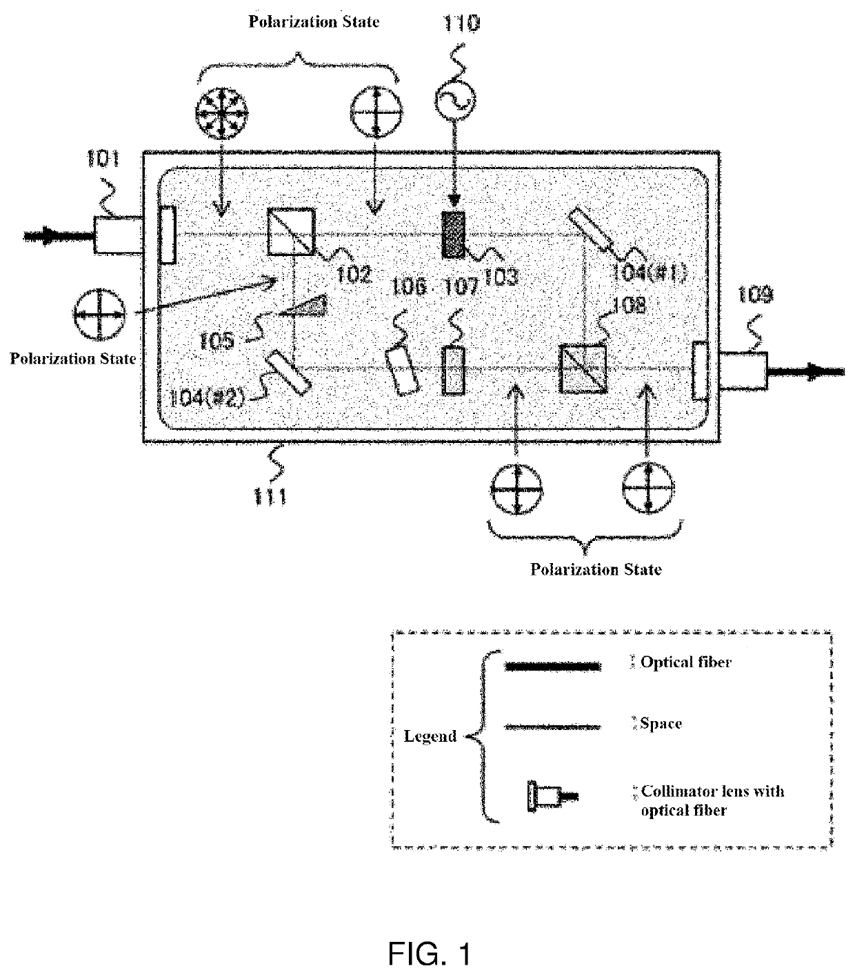
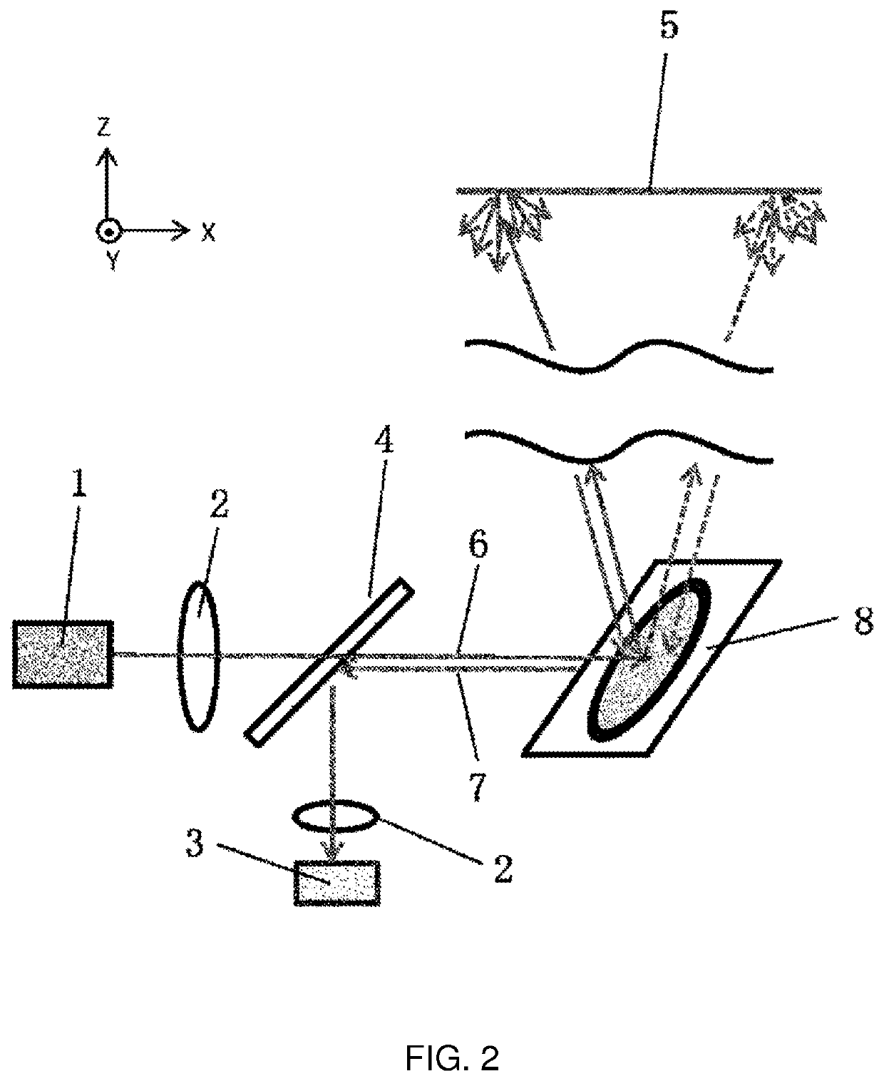
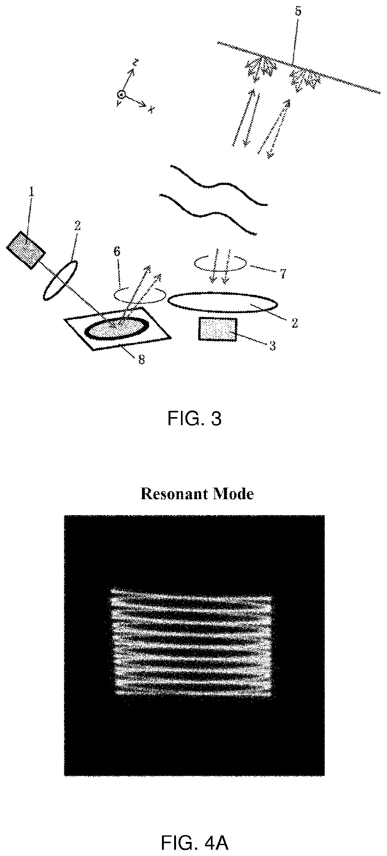
FIELD OF THE INVENTION[0001]The present invention relates to a circular polarization-type element and light beam digital scanning elements, and also to Lidar using these and a method for scanning.BACKGROUND OF THE INVENTION[0002]FIG. 1 is one embodiment example of polarization diversity as a conventional polarization control technology (Patent Document 1). After separating an incoming light into two orthogonal linearly polarized light beams with a polarizing beam splitter 102, one of the two light beams on one optical path is rotated by a polarization rotation element 107 thereby making the polarization of the light beams propagating on two optical paths the same (here, linearly polarized light beams oscillating vertically). However, although being effective for elements operating on linearly polarized light, this polarization diversity scheme may not be used for elements operating on circularly polarized light.[0003]Meanwhile, FIG. 2 shows a configuration of Lidar using a MEMS mirr...

Claims


Application Information

Patent Timeline
IPC IPC(8): G01S7/499G01S7/481G02B5/30G01S17/89G02B26/10
CPCG02B5/3025G01S17/89G01S7/499G01S7/4817G02B26/101G01S17/931G01S7/4812G01S7/4917G01S17/10G01S17/34G01S7/4814G02B27/283G02B27/4261G02F1/29G02B27/286
Inventor UETSUKA, HISATO
Owner NAT INST OF ADVANCED IND SCI & TECH
Learn More