Strain gauge stabilization in a surgical device

a strain gauge and surgical device technology, applied in the field of surgical devices, can solve the problems of signal loss, multiple cleaning and autoclave cycles, and incompatibility of end effectors with surgical devices and/or handle assemblies that use rotary motion, and achieve the effects of minimizing strain gauge error, stable temperature of strain gauge, and efficient dissipation

Active Publication Date: 2020-10-08
TYCO HEALTHCARE GRP LP
View PDF0 Cites 54 Cited by
  • Summary
  • Abstract
  • Description
  • Claims
  • Application Information

AI Technical Summary

Benefits of technology

[0013]To deal with heat transfer, the present disclosure uses a fluid, gel, or other electrically non-conductive, but thermally conducive material to maintain stable temperatures of the strain gauge. The present disclosure fills a cavity defined by a cover, which houses the strain gauge and the signal processing circuit, with a heat transferring composition. Due to additional heat transfer, this allows the signal processing circuit to be packaged in close proximity with the strain gauge, and for the heat generated by the signal processing circuit to be efficiently dissipated, which in turn, minimizes strain gauge error. Conventional configurations do not place the strain gauge in close thermal proximity to the signal processing circuit, so that heat produced by the signal processing circuit does not affect the temperature of the strain gauge. However, due to the novel design of placing the strain gauge within the same housing as the signal processing circuit, the present disclosure provides a solution to the additional heat being generated due to this configuration.

Problems solved by technology

As such, these end effectors are not compatible with surgical devices and / or handle assemblies that use rotary motion.
However, one limitation of the electronics and sensors used in the sterile environment of the operating room is that they need to be designed to withstand multiple cleaning and autoclave cycles.
Longer wired connections can result in signal loss and also increase the chances of failure due to exposure of these leads to disinfecting and sterilization cycles.
Harsh environments from disinfecting solutions and residual moisture from the autoclaving processes breaks down the components and coatings in flex circuits, thereby causing signal degradation.
Further, in surgical devices where saline irrigation is utilized, the saline can further breakdown of mechanical integrity of these circuits resulting in signal degradation.
In addition, the separation between the load sensing devices and the signal processing circuitry also affects fidelity of analog sense signals transmitted from the load sensing devices.
The analog voltage signals are low voltage signals and are therefore more susceptible to interference of the load measured by the load sensing devices due to water ingress in the PCB, solder connections, and / or traces, small contamination including solder flux and autoclave mineral deposits, as well as radio frequency interference due to long conductor travel length.
Remote placement of signal processing circuits also results in lower bit resolution.
Furthermore, conventional signal processing circuits used with load sensing devices have no ability to compensate for zero balance fluctuations in load sensing devices due to inconsistencies of sensor bodies housing the load sensing devices (e.g., during manufacture and assembly of the sensors).
Conventional load sensing devices that utilize strain gauge technology typically suffer from the lack of adjustability or tuning of the load sensing devices.
Unfortunately, in conventional load sensing devices zero balance cannot be adjusted for each individual load sensing device.
More specifically, due to the sensitivity of strain gauges, any change in temperature, which in turn affects electrical conductivity of the strain gauge or the signal processing circuit can introduce errors in the measurement signal.
This can be especially problematic because the signal processing circuit and the strain gauge generate heat when operated due to transmission of electrical signals therethrough.

Method used


Image

  • Strain gauge stabilization in a surgical device
  • Strain gauge stabilization in a surgical device
  • Strain gauge stabilization in a surgical device

Examples


Embodiment Construction

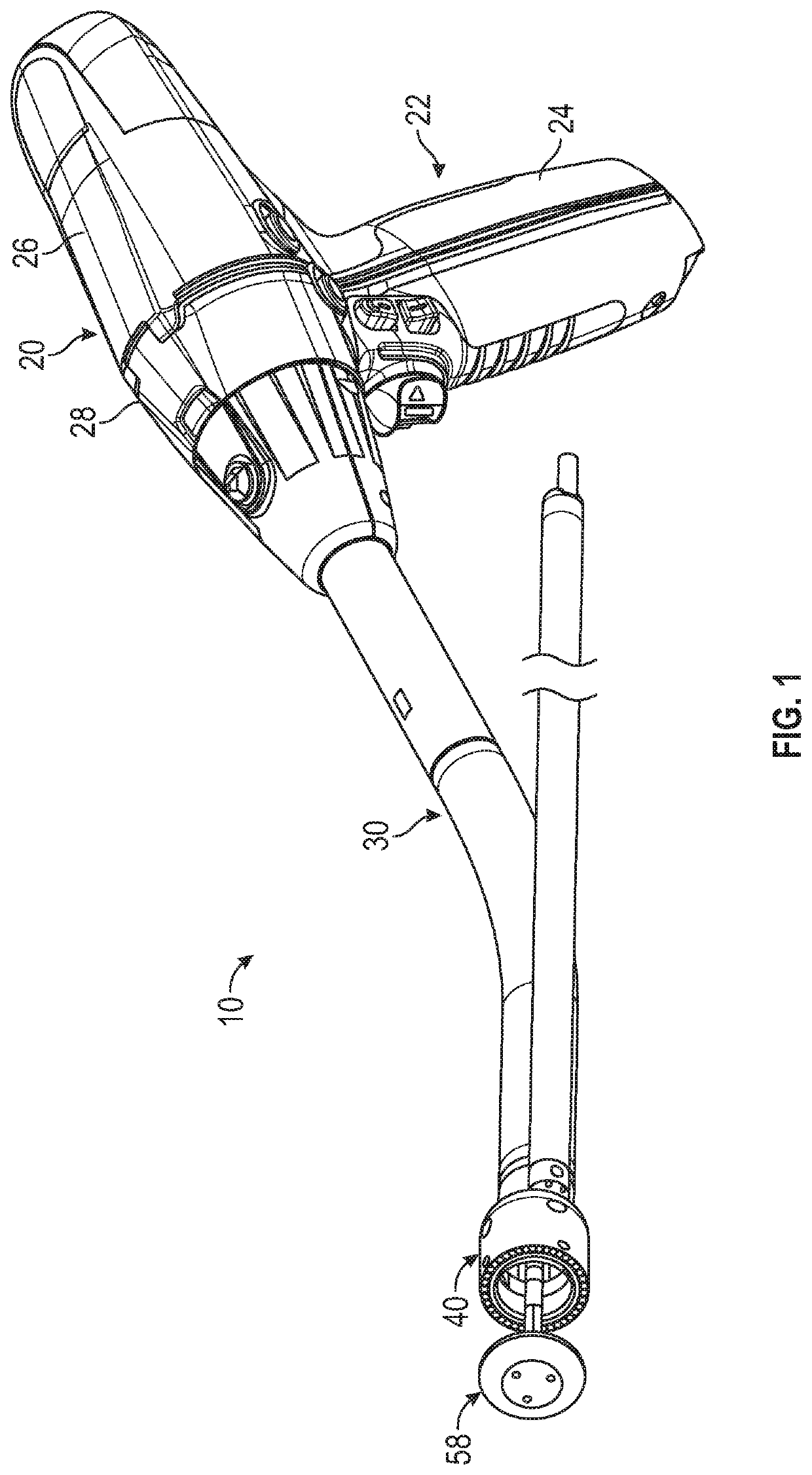
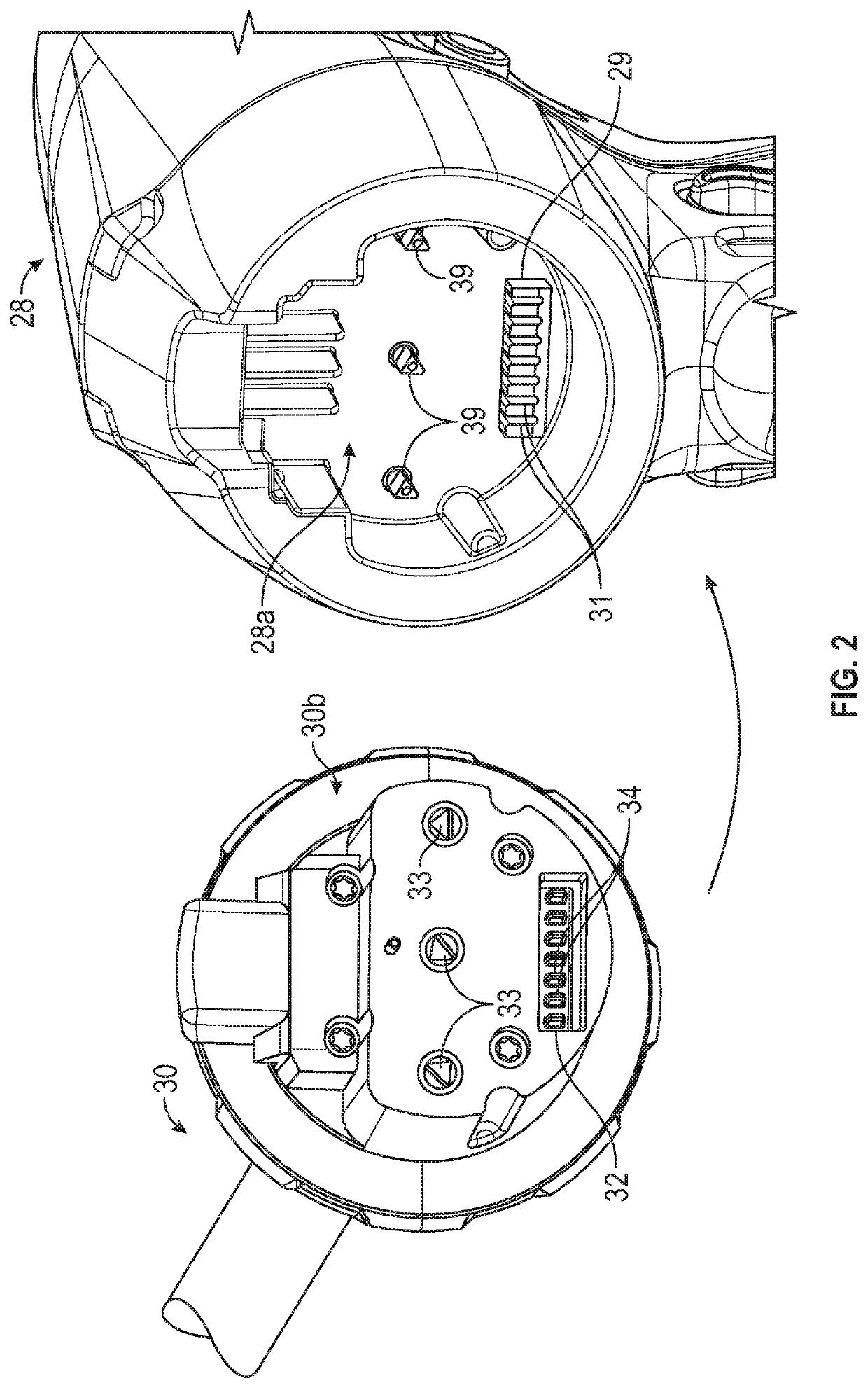
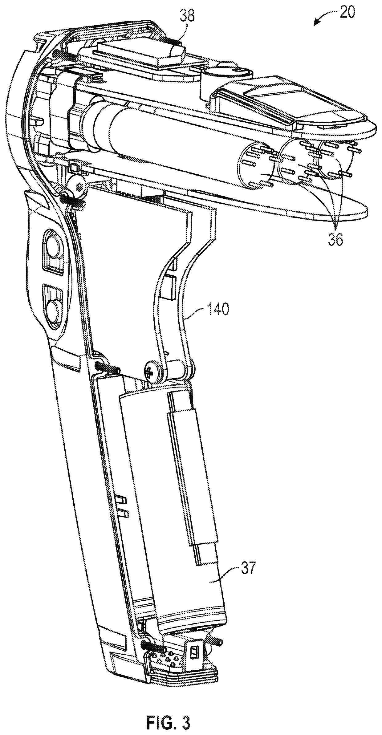
[0041]Embodiments of the present disclosure are now described in detail with reference to the drawings in which like reference numerals designate identical or corresponding elements in each of the several views. As used herein, the term “clinician” refers to a doctor, a nurse or any other care provider and may include support personnel. Throughout this description, the term “proximal” will refer to the portion of the device or component thereof that is closer to the clinician and the term “distal” will refer to the portion of the device or component thereof that is farther from the clinician. Additionally, in the drawings and in the description that follows, terms such as front, rear, upper, lower, top, bottom, and similar directional terms are used simply for convenience of description and are not intended to limit the disclosure. In the following description, well-known functions or constructions are not described in detail to avoid obscuring the present disclosure in unnecessary ...


PUM


Abstract

A surgical device includes an adapter assembly including a tubular housing having a proximal end portion configured to couple to a handle assembly, and a load sensing assembly disposed with the tubular housing. The load sensing assembly is configured to measure a load exerted on the tubular housing and includes: a sensor body including a pocket defined therein; a load sensor circuit disposed within the pocket and coupled to the sensor body; a signal processing circuit disposed within the pocket and electrically coupled to the load sensor circuit; a cover defining a cavity and disposed over the pocket and enclosing the load sensor circuit and the signal processing circuit therein, the cover being coupled to the sensor body thereby forming a first hermetic seal therebetween; and a thermal management material disposed within the cavity and in contact with the load sensor circuit and the signal processing circuit.

Description

CROSS-REFERENCE TO RELATED APPLICATIONS[0001]This application claims the benefit of and priority to U.S. Provisional Patent Application Ser. No. 62 / 829,698 filed Apr. 5, 2019, the entire disclosure of which is incorporated by reference herein.BACKGROUND1. Technical Field[0002]The present disclosure relates to surgical devices. More specifically, the present disclosure relates to handheld electromechanical surgical systems for performing surgical procedures having reusable components with load sensing devices.2. Background of Related Art[0003]One type of surgical device is a circular clamping, cutting and stapling device. Such a device may be employed in a surgical procedure to reattach rectum portions that were previously transected, or similar procedures. Conventional circular clamping, cutting, and stapling devices include a pistol or linear grip-styled structure having an elongated shaft extending therefrom and a staple cartridge supported on the distal end of the elongated shaft...

Claims


Application Information

Patent Timeline
Patent Type & Authority Applications(United States)
IPC IPC(8): A61B17/072
CPCA61B2562/0271A61B2017/07271A61B2017/00084A61B2017/00486A61B2562/0252A61B2562/0261A61B2017/00831A61B17/07207A61B2017/00473G01L1/2206G01L1/2281G01L1/2268G01L1/2262A61B17/11A61B17/32053A61B2017/00477A61B2017/1132A61B2017/00367A61B17/1155A61B2017/00017A61B2017/00398A61B2017/0046A61B2090/064A61B2090/0813A61B2562/00A61B2017/00725
Inventor EISINGER, JOSEPHVALENTINE, JR., DAVIDFIRTH, SCOTT
Owner TYCO HEALTHCARE GRP LP
Why Eureka
Try Eureka