
Lens-free compound eye cameras based on angle-sensitive meta-surfaces

a technology of meta-surfaces and lenses, applied in the field of lens-free compound eye imaging sensors, can solve the problems of inability to immediately integrate standard microelectronic circuits, complexity in fabrication, and difficulty in developing cameras based on this idea, and achieves the effects of large dynamic range, high acuity to motion, and infinite depth of field

Active Publication Date: 2020-10-08
TRUSTEES OF BOSTON UNIV
View PDF0 Cites 14 Cited by
  • Summary
  • Abstract
  • Description
  • Claims
  • Application Information

AI Technical Summary

Benefits of technology

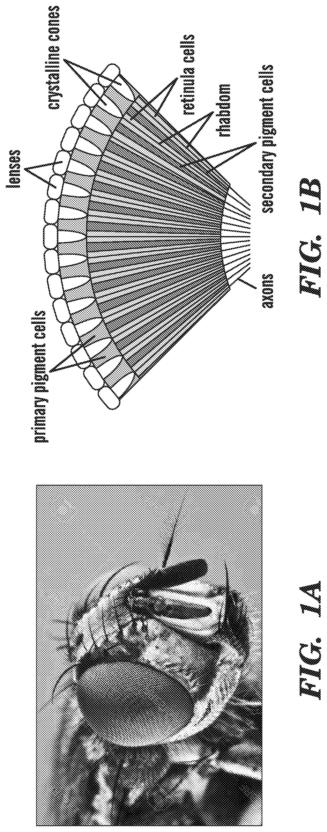
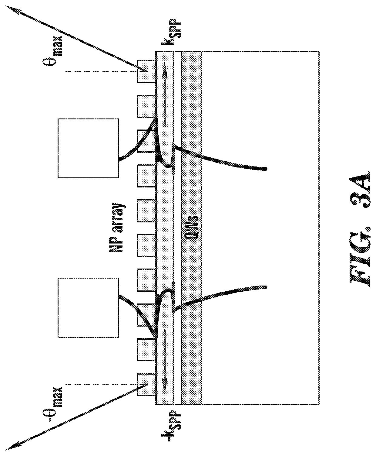
The present invention is a lens-free ultrathin imaging sensor that uses a compound-eye vision modality. It consists of an array of imaging elements that can detect only that portion of light incident on the element that propagates along a predefined angular direction. This design provides for extreme size miniaturization, high acuity to motion, and large dynamic range. Compared to traditional lens-based imaging sensors, it is lens-free and can be directly integrated with standard CMOS or CCD image sensor arrays. It also has the advantage of being intrinsically polarization sensitive. The metasurface can be designed to transmit into its photosensitive substrate light incident along a few selected directions, which can improve resolution with advanced signal processing. The nanoantennas in the metasurface can be fabricated using dielectric materials instead of metals to improve peak transmission at the desired angle of incidence. The fabrication process can be simplified by using an ultrathin film without slits and a dielectric coating on the top surface to produce phase matching between surface plasmon polaritons guided on both sides of the film.

Problems solved by technology

So far, however, the development of practical cameras based on this idea has been hindered by fabrication complexity, mostly related to the critical need for accurate alignment between the two arrays and challenges caused by the formation of ghost images.
Furthermore, designs involving curved substrates are not immediately compatible with standard microelectronic circuits.

Method used


Image

  • Lens-free compound eye cameras based on angle-sensitive meta-surfaces
  • Lens-free compound eye cameras based on angle-sensitive meta-surfaces
  • Lens-free compound eye cameras based on angle-sensitive meta-surfaces

Examples


Embodiment Construction

[0044]The present invention is directed to imaging sensors (e.g. for cameras) that can provide fast panoramic vision across a wide field of view using a highly miniaturized platform. Specific application areas that would greatly benefit from these features include machine vision, surveillance, and endoscopic medical imaging. For example, cameras according to the invention can be used to sense the relative motion between an observer and its surroundings, and therefore can be used in cars and other terrestrial or aerial vehicles for obstacle or collision avoidance, surveillance, and ultimately autonomous navigation. Extreme size miniaturization in this context is particularly interesting for the development of microscopic aircrafts directly inspired by flying insects. Similarly, again because of their small size and large field of view, the cameras according to the invention can provide enhanced imaging capabilities in constricted or nontraditional environments such as chip-on-the-tip...


PUM

PropertyMeasurementUnit
thicknessaaaaaaaaaa
distanceaaaaaaaaaa
heightaaaaaaaaaa

Abstract

A lens-free ultrathin imaging sensor using a compound-eye vision modality can be formed by forming a metasurface on each pixel of an array of pixels in a solid state imaging sensor. The metasurface can be configured to form a diffraction grating that directs light incident on the metasurface at a predefined angle to excite surface plasmon polaritons into the solid state imaging sensor and light incident at any other angle is reflected or diffracted away from the metasurface. Each pixel of the imaging sensor can be configured using the metasurface to only receive light incident from a different portion of a field of view. A computational imaging system can be used to construct the image from the individual pixels.

Description

CROSS-REFERENCE TO RELATED APPLICATIONS[0001]This application claims any and all benefits as provided by law including benefit under 35 U.S.C. § 119(e) of the U.S. Provisional Application No. 62 / 571855 filed Oct. 13, 2017, the contents of which are incorporated herein by reference in its entiretySTATEMENT REGARDING FEDERALLY SPONSORED RESEARCH[0002]This invention was made with government support under grant no. DE-FG02-06ER46332 awarded by U.S. Department of Energy. The government has certain rights in the invention.REFERENCE TO MICROFICHE APPENDIX[0003]Not ApplicableBACKGROUNDTechnical Field of the Invention[0004]The present invention is directed to a lens-free compound eye imaging sensor that includes a plurality of pixels and each pixel includes a metasurface configured to allow only light incident at a predefined angle to be detected. By configuring each pixel to only receive light from a different portion of the field of view, an image of the field of view can be constructed fr...

Claims


Application Information

Patent Timeline
Patent Type & Authority Applications(United States)
IPC IPC(8): H01L27/146G02B5/18H01L31/028
CPCG02B5/1828H01L27/1462H01L27/1463H01L27/14625H01L31/028H01L31/02327H01L31/09
Inventor PAIELLA, ROBERTOKOGOS, LEONARD
Owner TRUSTEES OF BOSTON UNIV
Learn More