On-board electric compressor

a technology of electric compressor and motor, which is applied in the direction of positive displacement liquid engine, pump, lighting and heating apparatus, etc., can solve the problems of inability of inverter device to perform power conversion, affecting the operation of on-board motor-driven compressor, and common mode noise and normal mode nois

Active Publication Date: 2020-10-08
TOYOTA IND CORP
View PDF0 Cites 5 Cited by
  • Summary
  • Abstract
  • Description
  • Claims
  • Application Information

AI Technical Summary

Benefits of technology

[0016]The present invention reduces the common mode noise and normal mode noise that are included in the DC power in a preferred manner.

Problems solved by technology

However, common mode noise and normal mode noise may both be mixed in the DC power before being input to the inverter device.
In such a case, the inverter device may not be able to perform power conversion in a normal manner because of such noise.
This may hinder the operation of the on-board motor-driven compressor.
In particular, the frequency of the normal mode noise differs between the type of vehicle on which the on-board motor-driven compressor is mounted.

Method used


Image

  • On-board electric compressor
  • On-board electric compressor
  • On-board electric compressor

Examples


first embodiment

[0032]One embodiment of an on-board motor-driven compressor will now be described. The on-board motor-driven compressor of the present embodiment is used in an on-board air conditioner. That is, fluid compressed by the on-board motor-driven compressor is a refrigerant.

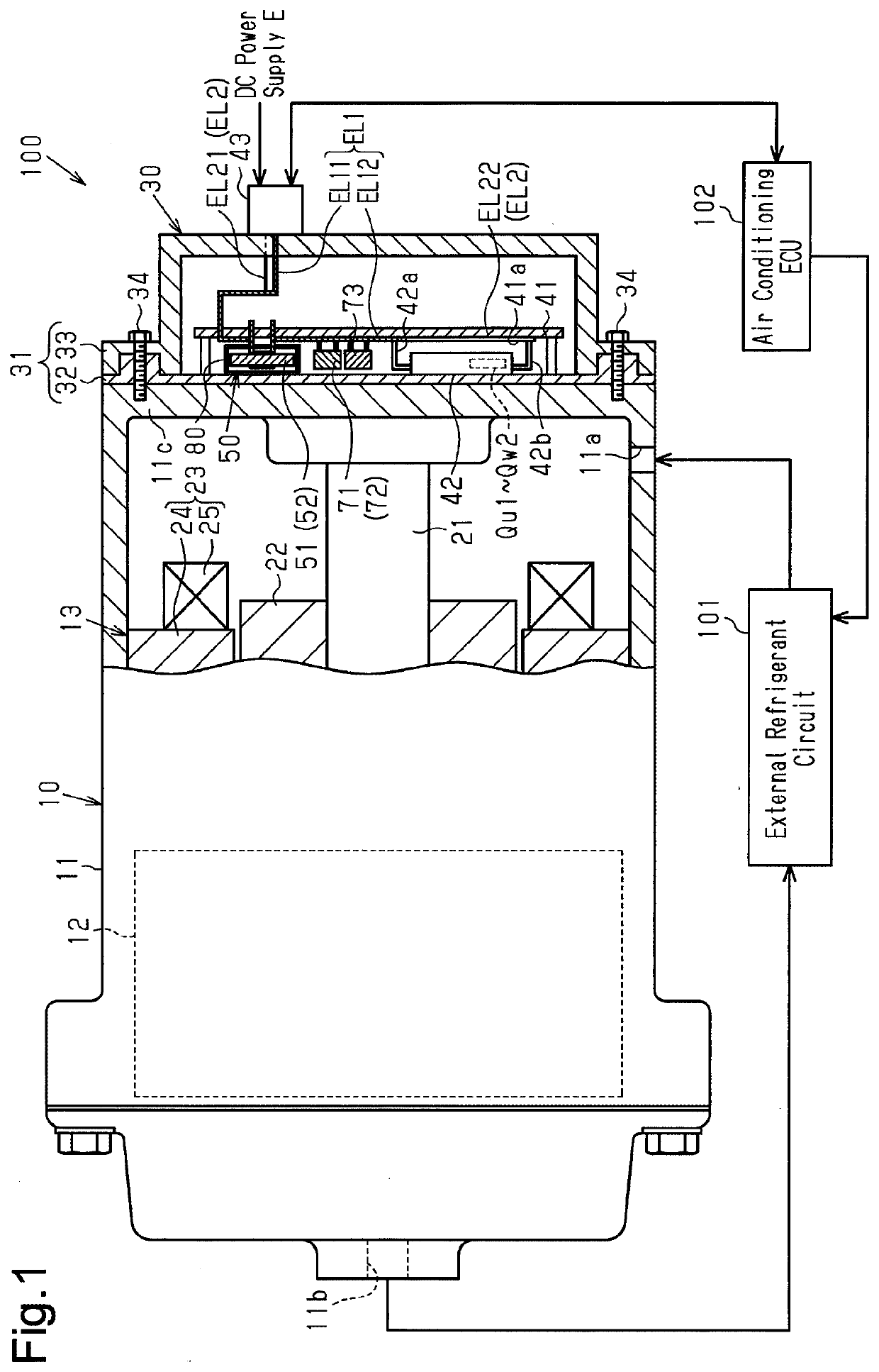
[0033]As shown in FIG. 1, an on-board air conditioner 100 includes an on-board motor-driven compressor 10 and an external refrigerant circuit 101 that supplies the on-board motor-driven compressor 10 with the refrigerant serving as the fluid. The external refrigerant circuit 101 includes, for example, a heat exchanger, an expansion valve, and the like. The on-board air conditioner 100 cools and warms the passenger compartment by compressing the refrigerant with the on-board motor-driven compressor 10 and carrying out heat exchange and expansion of the refrigerant with the external refrigerant circuit 101.

[0034]The on-board air conditioner 100 includes an air conditioning ECU 102 that controls the entire on-board air co...

second embodiment

[0141]A second embodiment will now be described focusing on differences from the first embodiment and the example.

[0142]FIGS. 11, 12, and 13 show a noise reducing unit (damping unit 200) according to a second embodiment.

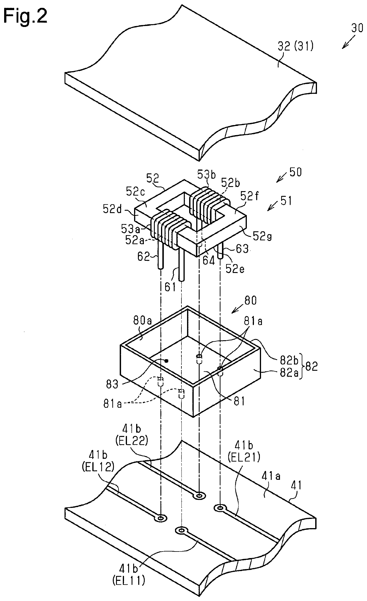
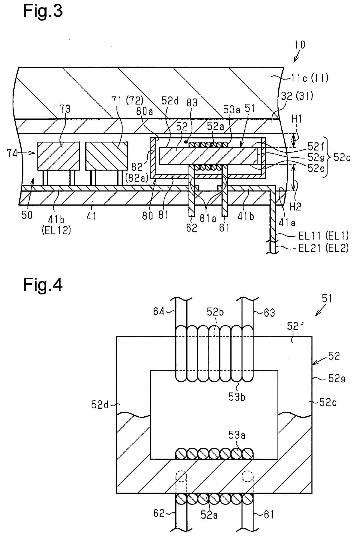
[0143]In the first embodiment, the damping unit 80 shown in FIGS. 2 and 3 is box-shaped and includes the opening 80a covered by the inverter case 31 and the bottom portion (end wall), and the common mode choke coil 51 is accommodated in the accommodation compartment 83 defined by the damping unit 80 and the inverter case 31 to lower the Q value of the low pass filter circuit 74. However, when mounting the common mode choke coil 51 on the circuit board 41, it may be difficult to cover the six surfaces of the common mode choke coil 51 with metal.

[0144]In the second embodiment, plating is performed on the common mode choke coil 51 so that the common mode choke coil 51 is covered with a shield electrically conductive metal film 210, and the damping unit 200 includes a sh...

third embodiment

[0149]A third embodiment will now be described focusing on differences from the first embodiment and the examples.

[0150]FIGS. 14 and 15 show a noise reducing unit (damping unit 300) according to a third embodiment.

[0151]In the first embodiment, the common mode choke coil 51 is accommodated in the accommodation compartment 83 defined by the box-shaped damping unit 80 including the opening 80a and the bottom portion (end wall) and the inverter case 31 to lower the Q value of the low pass filter circuit 74, as shown in FIGS. 2 and 3. However, when mounting the common mode choke coil 51 on the circuit board 41, it may be difficult to cover the six surfaces of the common mode choke coil 51 with metal.

[0152]In the third embodiment, in the common mode choke coil 51, one of the six surfaces is covered with a pattern conductor (copper foil) 320 of the circuit board 41, and the other five surfaces are covered with a shield electrically conductive metal case 310 including an opening 311. That ...


PUM


Abstract

An on-board electric compressor that comprises: a housing; a compression unit; an electric motor; and an inverter device. The inverter device comprises: an inverter circuit that converts direct current power to alternating current power; and a noise reduction unit that is provided on an input side of the inverter circuit and that reduces common mode noise and normal mode noise that are included in the direct current power The noise reduction unit comprises: a common mode choke coil; and a smoothing capacitor that, in cooperation with the common mode choke coil, constitutes a low pass filter circuit. The common mode choke coil has: a core that has a first core part and a second core part; a first winding that is wound around the first core part; and a second winding that is wound around the second core part.

Description

TECHNICAL FIELD[0001]The present invention relates to an on-board motor-driven compressor (a motor-driven compressor configured to be installed in a vehicle).BACKGROUND ART[0002]An on-board motor-driven compressor including a compression unit, an electric motor that drives the compression unit, and an inverter device that drives the electric motor is known in the art (for example, refer to patent document 1).PRIOR ART DOCUMENTPatent Document[0003]Patent document 1: Japanese Patent No. 5039515SUMMARY OF THE INVENTIONProblems that are to be Solved by the Invention[0004]The inverter device converts direct current (DC) power to alternating current (AC) power. However, common mode noise and normal mode noise may both be mixed in the DC power before being input to the inverter device. In such a case, the inverter device may not be able to perform power conversion in a normal manner because of such noise. This may hinder the operation of the on-board motor-driven compressor.[0005]In partic...

Claims


Application Information

Patent Timeline
Patent Type & Authority Applications(United States)
IPC IPC(8): H02K11/33H03H7/01H02K11/22F25B31/02
CPCH02K2211/03F25B31/026H02K11/022H02K11/33H03H7/0115H02M7/48H03H7/09H02M1/123F04B35/04H02M1/44H02M1/126H02K11/02F04B49/065H02M1/12H02M7/003H02M1/0064H02K11/01
Inventor KAGAWA, FUMIHIRONAITO, ATSUSHINAGATA, YOSHIKIAMBO, SHUNSUKEYASHIRO, KEIJISHIRAISHI, KAZUHIRO
Owner TOYOTA IND CORP
Why Eureka
Try Eureka