Apparatus and method for material processing

a material processing and apparatus technology, applied in the field of apparatus and method for material processing, can solve the problems of discrepancy, variability, annular redistribution of radiation, complex manufacturing process, etc., and achieve the effect of cost-effectiveness, generating aberrations and changing more efficiently

Inactive Publication Date: 2020-10-22
PETRING DIRK +3
View PDF1 Cites 1 Cited by
  • Summary
  • Abstract
  • Description
  • Claims
  • Application Information

AI Technical Summary

Benefits of technology

[0036]Such a device as well as a method according to the invention allows to dispense with sensitive fiber and diffraction optics for beam shaping, to continuously change the beam quality and thus also the beam distribution with high variability and also to use cost-effective optics made of high-quality substrates and having good coating characteristics.
[0040]The apparatus according to the invention can also be used in particular if the radiation entering the beam-shaping optics with the first beam parameter product is non-collimated radiation. This eliminates the need for collimation optics without significantly increasing the technical expenditure to dimension the optical elements of the beam-shaping optics. The expenditure can be even lower, since in principle a usual parallelization of the radiation can be omitted using the apparatus according to the invention.
[0044]The at least one first and / or the at least one second optical element, or even another optical element, of the beam-shaping optics can have spherical surfaces, thereby significantly reducing the manufacturing costs.
[0046]The optical properties of the at least one first optical element and / or the at least one second optical element, or even of another optical element, can be varied by changing the refractive index thereof, the refractive index gradient thereof or the shape thereof, i.e. the shape of the surface(s) of the optical elements. It is advantageous in each case to use the variation method that allows for the desired variation of the beam parameter product in the best and most cost-effective manner. Thus, optics with a variable refractive index or with variable refractive index gradients based on semiconductor materials or liquids (so-called liquid lenses) can be used for the low power range below 100 watts, while for high power in the range above 5 kW, mirror optics with a membrane that reflects the radiation and is deformable via piezo drives or via varying pressure of an internal medium (water, air, oil) may be advantageous.
[0047]A negative optical focal length in relation to the at least one first optical element or the at least one second optical element, or also in relation to another optical element, results in the radiation being widened and, in interaction with positive optical elements, aberrations can be generated and changed more efficiently due to the then more easily changeable phase shifts of the wave front of the radiation.

Problems solved by technology

Fiber optics (or waveguides) are very sensitive at their inlet and outlet due to the high power densities of the radiation used at the respective end faces and require expensive, high-precision adjustable coupling optics and allow only limited, sometimes even only discrete, variability of beam shaping.
Axicons, i.e. special conically ground lenses or mirrors that transform circular radiation into a ring, as well as so-called Siemens star optics, which are made up of radial facets running in a zig-zag pattern in the circumferential direction and thus also cause an annular redistribution of radiation that is, however, interrupted along the circumference of the ring, are very complex in terms of the manufacturing process, especially with regard to mold production, polishing and coating, and are very sensitive to adjustment.
Variable diffraction optics, as employed in the prior art, allow variable beam-shaping or spatial light modulation only in the low power range, since semiconductor elements available today, with which the phase shift can be changed locally, generate too high thermal losses, which at higher power densities lead to malfunctions or even destruction of the sensitive optics.
The document mentioned even limits itself to only “scored”, i.e. fixed non-variable diffractive optics, whose power handling capacity is also very limited and which, like all diffractive optics, also cause system-immanent diffraction losses.
Optics in addition to the standard optics, which consists of collimating and focusing optics, whereby the additional optics are arranged in front of the collimating optics, unnecessarily increase the overall optical system and the number of optical elements.
In addition, the boundary conditions specified by the standard configuration unnecessarily restrict the beam-shaping variation range that can be generated with reasonable effort.
Thermo-optical elements, as used according to the prior art, allow only a sluggish and comparatively inaccurate variation of the beam distribution.
Incrementally, discretely moving optics, for example in the form of revolver optics or optics switching to different fibers, which only switch between discrete optical states, are thus significantly limited in terms of their variability.

Method used


Image

  • Apparatus and method for material processing
  • Apparatus and method for material processing
  • Apparatus and method for material processing

Examples


first embodiment

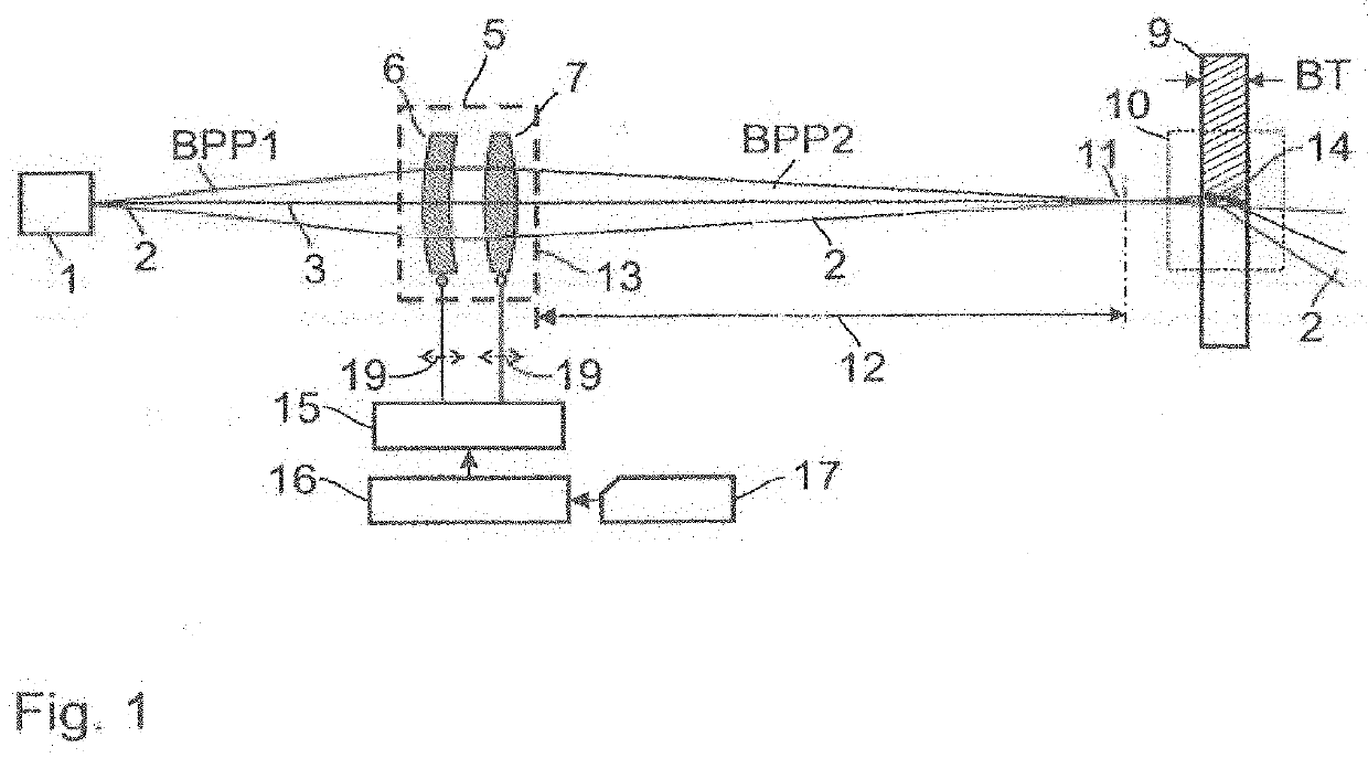
[0067]The apparatus according to the invention, as illustrated in FIG. 1 comprises a beam source 1 emitting electromagnetic radiation 2, the beam axis of which is designated by the reference mark 3. Radiation 2 has a defined power density distribution with a first beam parameter product BPP1. The divergent radiation 2 from beam source 1 enters beam-shaping optics 5 as non-collimated radiation.

[0068]The beam-shaping optics 5 serves to variably shape and focus the radiation 2 and has at least one first optical element 6 and at least one second optical element 7. In the example shown, the first optical element 6 of this beam-shaping optics 5 is a meniscus lens, while the second optical element 7 of the beam-shaping optics 5, which is positioned behind the first optical element 6 when viewed in the direction of radiation 2, is a biconvex converging lens.

[0069]Thus in the first embodiment of FIG. 1, the first optical element 6 and the second optical element 7 of the beam-shaping optics ...

second embodiment

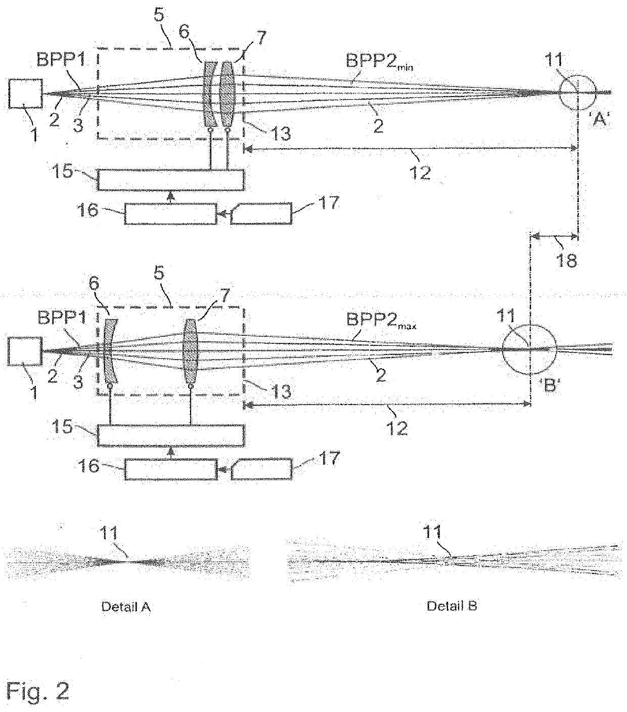
[0083]FIG. 2 shows a device according to the invention. On the basis of FIG. 2, the characteristics and features of the invention regarding the change of the second beam parameter product BPP2 and the waist distance 12 are explained in more detail.

[0084]Also in the embodiment of FIG. 2, the beam-shaping optics 5 is composed of a first optical element 6 in the form of a meniscus lens and a second optical element 7 in the form of a biconvex lens. The small distance between the two optical elements 6 and 7 results in low aberration focusing of the emitted radiation 2, so that a beam waist 11 of the focused radiation at a waist distance 12 results, which has a small expansion, as shown in detail A. In this case, a minimum second beam parameter product BPP2min is associated with radiation 2 on the output side of beam-shaping optics 5; this is defined as the second beam parameter product BPP2 in which the product of beam waist radius (rF) and beam divergence assumes a minimum value, so th...

third embodiment

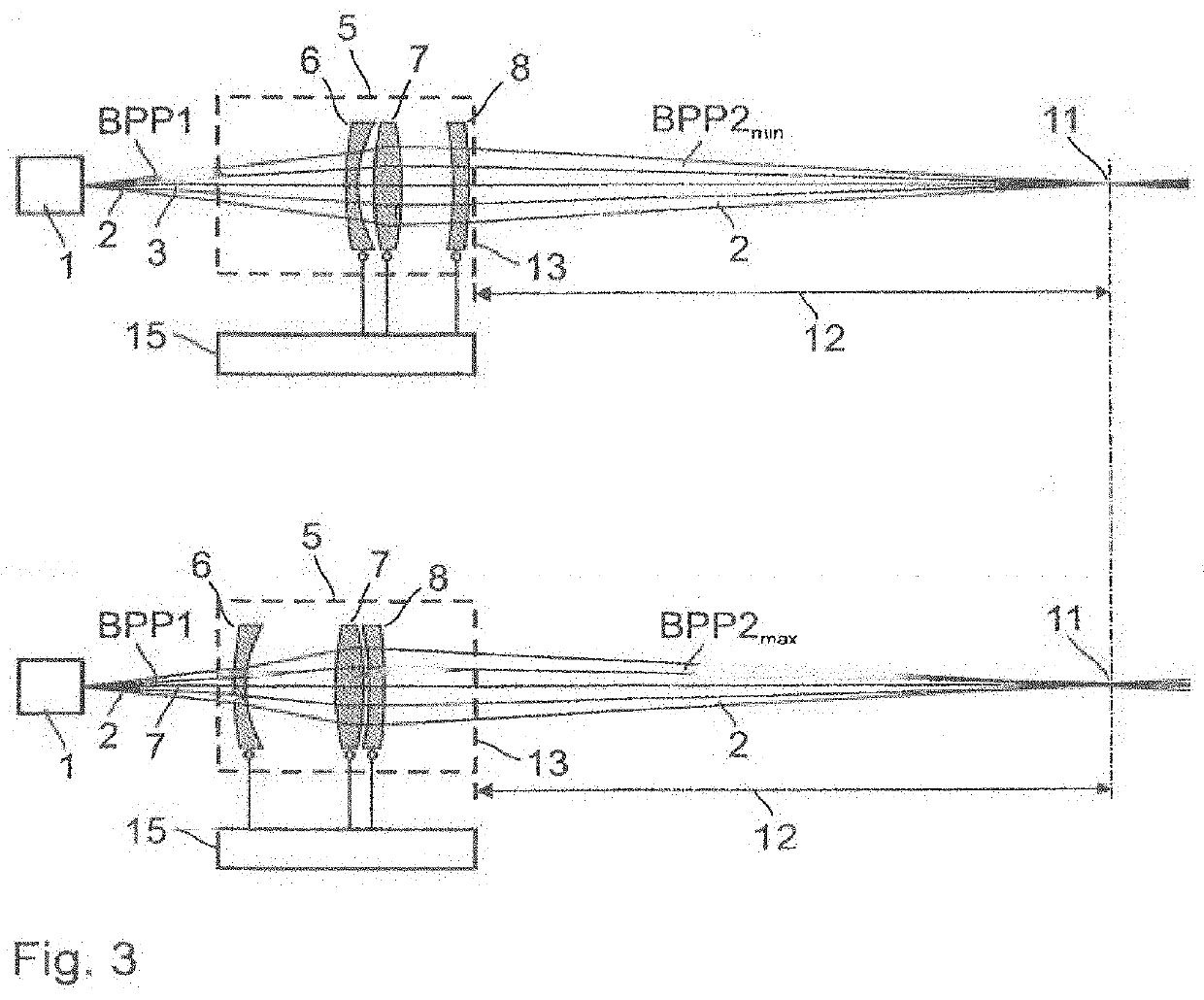
[0095]In FIG. 3, which shows the apparatus according to the invention, the beam-shaping optics 5 has, in addition to the first optical element 6 and the second optical element 7, a third optical element 8 on the output side of the second optical element 7, the position of which can be changed by means of the adjusting device 15. In FIG. 3, the third optical element 8 is a convex-concave lens and is located, for example, close to reference plane 13, while the first and second optical elements 6, 7 are at a small distance from each other, as shown in the upper illustration in FIG. 3. The third optical element 8 of the beam-shaping optics 5 serves to compensate for the change in waist distance 12, which occurs during variation of the beam parameter product BPP2 by shifting the first and second optical elements 6 and 7, and ideally to keep it constant. By arranging the optical elements 6, 7 and 8 within the beam-shaping optics 5, a minimum value of the beam parameter product BPP2 is set...


PUM

PropertyMeasurementUnit
power density distributionaaaaaaaaaa
optical propertyaaaaaaaaaa
optical propertiesaaaaaaaaaa

Abstract

Apparatuses and methods for material processing are disclosed. In an embodiment, an apparatus may include a source of electromagnetic radiation that emits the radiation in a beam with a defined power density distribution and beam-shaping optics variably shaping and focusing the radiation of the beam source. An optical axis of the radiation may be directed onto a processing zone. The apparatus may also include means for holding the radiation in a region wherein the radiation interacts with a material forming and moving in the processing zone; as well as an adjusting device that varies the second beam parameter product by changing at least one of a position and an optical property of at least one optical element. In an embodiment, a first optical element of the beam-shaping optics generates or increases the amount of an aberration; and a second optical element of the beam-shaping optics changes an amount of an aberration generated or increased by changing, using the adjusting device, a position or optical properties the first and / or the second optical element, such that the second beam parameter product is adjusted.

Description

CROSS REFERENCE TO RELATED APPLICATIONS[0001]This application claims priority to International Application No. PCT / EP2018 / 000419, published as WO2019 / 042581, the disclosure of which is incorporated herein in its entirety.INTRODUCTION[0002]The invention relates to an apparatus and method for material processing.[0003]Such a device for material processing has at least one beam source of electromagnetic radiation, which emits radiation with a defined power density distribution. The radiation from the beam source is guided by beam-shaping optics that variably shape and focus the radiation. The optical axis of the focused radiation, also referred to as the beam axis, is directed onto a processing zone. Furthermore, devices are present that keep the radiation in the area of the interaction surface of radiation and material that is forming and moving in the processing zone. The emitted radiation has a first beam parameter product and the radiation in the processing zone where the radiatio...

Claims


Application Information

Patent Timeline
Patent Type & Authority Applications(United States)
IPC IPC(8): B23K26/06G02B27/00G02B27/30G02B27/09G02B19/00B23K26/073
CPCB23K26/073G02B27/0955G02B19/0014G02B19/0047B23K26/0665B23K26/21B23K26/36B23K26/0648G02B27/0025G02B27/30G02B19/0009B23K26/38G02B19/0023
Inventor PETRING, DIRKSCHNEIDER, FRANKSTOYANOV, STOYAN
Owner PETRING DIRK
Why Eureka
Try Eureka