

High capacitance composites
a composite and high capacitance technology, applied in the field of high capacitance composites, can solve the problems of low edlc energy density, low specific capacitance of specific capacitance, and low surface area alone, and achieve the effect of high surface area, low volumetric mass density, and superior performance of supercapacitors
- Summary
- Abstract
- Description
- Claims
- Application Information
AI Technical Summary
Benefits of technology
Problems solved by technology
Method used
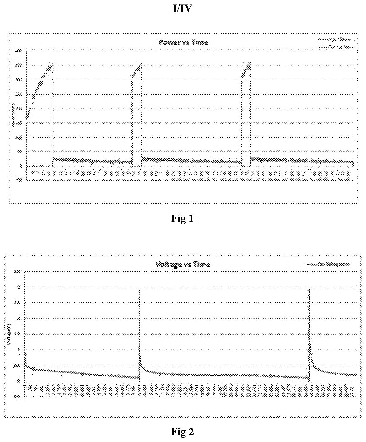
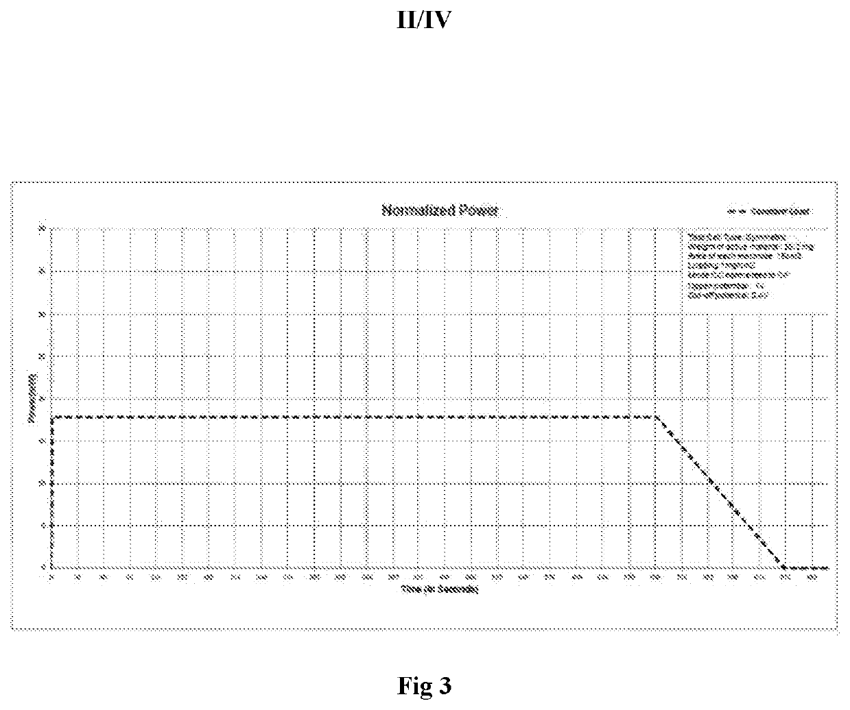
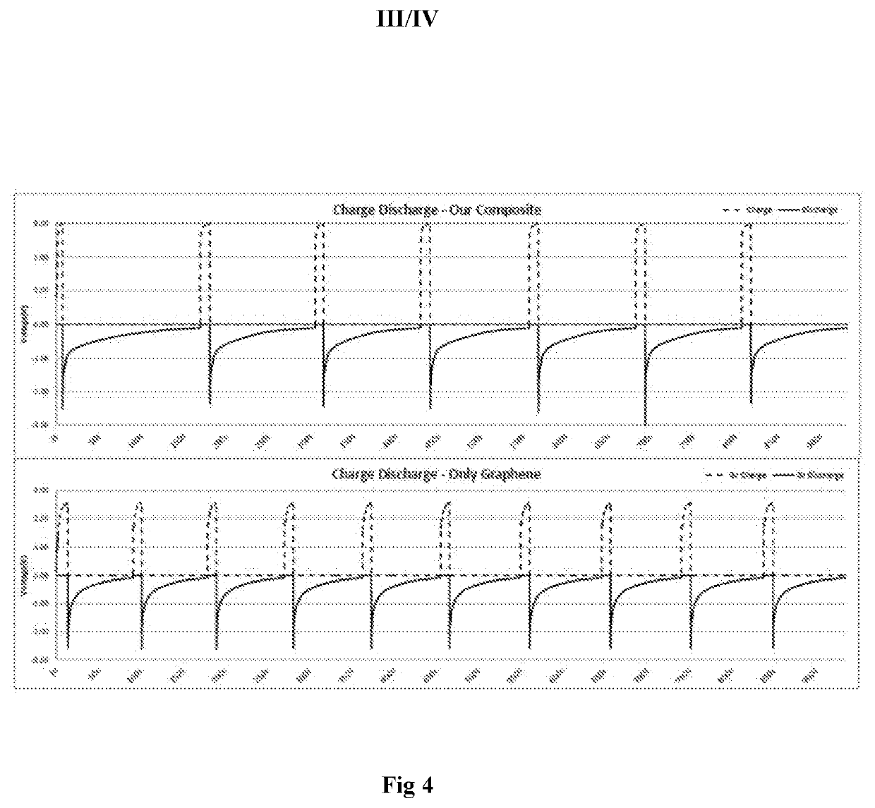
Image

Examples
example 1
Preparation of the Composite
Example 1a
Synthesis of Graphene Using Mechanical Exfoliation
[0154]10 grams of 2000 mesh graphite was added per litre of solvent mixture of water and ethanol in 10:1 (v / v) ratio. pH was adjusted to 12-13 by addition of sodium hydroxide. The graphite was kept in suspension and stirred until a pitch black solution containing 1-2 layers of graphene flakes were obtained. The graphene remained in suspension even after 4 weeks with negligible loss in concentration. A concentration of 0.92 mg / ml was determined at the end of 4 weeks.
example 1b
Synthesis of Mesoporous Carbon by Chemical Activation
[0155]The carbon precursor was mixed with KOH in 1:1 molar ratio and calcined to a temperature of 980° C. The residual chemicals present on or in the carbon were rinsed with HCl (35%; 200 ml) followed by rinsing excessively with deionized water (2000 ml) to obtain mesoporous carbon.
[0156]BET Surface area: >1400 m2 / g.
example 1c
Synthesis of Graphitic Carbon Nitride Coated on to Mesoporous Carbon (mc@g-C3N4)
[0157]Mesoporous carbon of step lb was micronized in a ball mill for 20 hours to obtain particle size between 5-20 um. 90 g Urea was then mixed with 10 g of micronized mesoporous carbon powder. 60 mL water was added to make a saturated urea solution. This mixture was then sonicated in an ultrasonic bath (150 W) for 120 minutes. The resulting solution was then calcinated at 520° C. for 360 minutes to obtain the mc@g-C3N4. The material showed itself as a very low density high volume material. The powder was put in the ball mill to break up any agglomerates and sifted through a 10 micron mesh to obtain the final fine powder for use in the electrode. The final density was 0.16 g / cm3.
PUM
| Property | Measurement | Unit |
|---|---|---|
| thickness | aaaaa | aaaaa |
| thickness | aaaaa | aaaaa |
| conductivity | aaaaa | aaaaa |
Abstract
Description
Claims
Application Information