Continuous self-test of a gyroscope

a self-testing, gyroscope technology, applied in the direction of speed measurement using gyroscopic effects, instruments, surveying and navigation, etc., can solve the problems of limiting the speed of the feedback loop and the bandwidth of the angular rate sensor, so as to achieve fast error detection time, good detection coverage, and efficient immunity

Active Publication Date: 2020-12-24
MURATA MFG CO LTD
View PDF0 Cites 9 Cited by
  • Summary
  • Abstract
  • Description
  • Claims
  • Application Information

AI Technical Summary

Benefits of technology

[0030]The present invention has the advantage that it provides a robust continuous self-test with efficient immunity towards any external inertial signals, as long as they are not strong enough to inflict unwanted mechanical contact within the MEMS gyroscope, in other words exceeding the MEMS gyroscope's defined operation range. The present invention also allows fast error detection time, typically below 5 ms. Further, the present invention requires only modest test signal level despite robust operation while providing good detection coverage.

Problems solved by technology

Thus, the speed of the feedback loop and the bandwidth of the angular rate sensor becomes limited.
Also, this solution the closed sense loop includes both modulations and demodulations both in angular rate and quadrature phase, which requires an additional filter for removing primary frequency signal content from the signal before modulation, which limits the speed of the feedback loop and the bandwidth of the angular rate sensor.

Method used


Image

  • Continuous self-test of a gyroscope
  • Continuous self-test of a gyroscope
  • Continuous self-test of a gyroscope

Examples


first embodiment

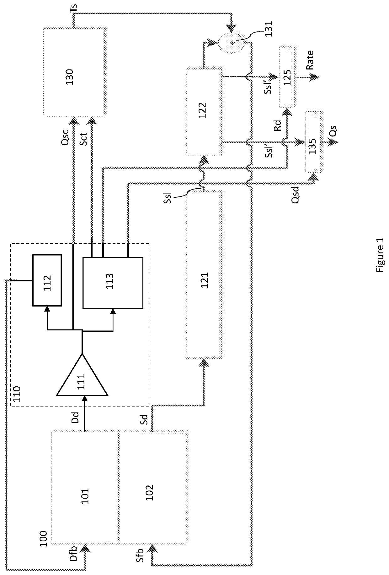
[0041]The FIG. 1 shows a top-level block diagram of a gyroscope that is of closed-loop type.

[0042]The gyroscope sensor element (100) comprises a drive element (101) and a sense element (102). Both the drive element (101) and the sense element (102) comprise detection means, such as a capacitive, piezoelectrical or piezoresistive transducer, that detects motion of the element and converts that into an electrical signal, and feedback means that may be used for controlling oscillation of the respective element (101; 102).

[0043]A first closed-loop system, called as the primary loop or the drive loop, controls driving of the drive element (101) into a stable mechanical oscillation at a primary frequency fprim. Feedback enables controlling the drive motion. In case the sensor element (100) is a capacitive sensor element, drive loop electronics (110) may comprise a charge-sensitive amplifier, drive loop front-end (111) that may comprise for example a charge sensitive amplifier, CSA, that ...

second embodiment

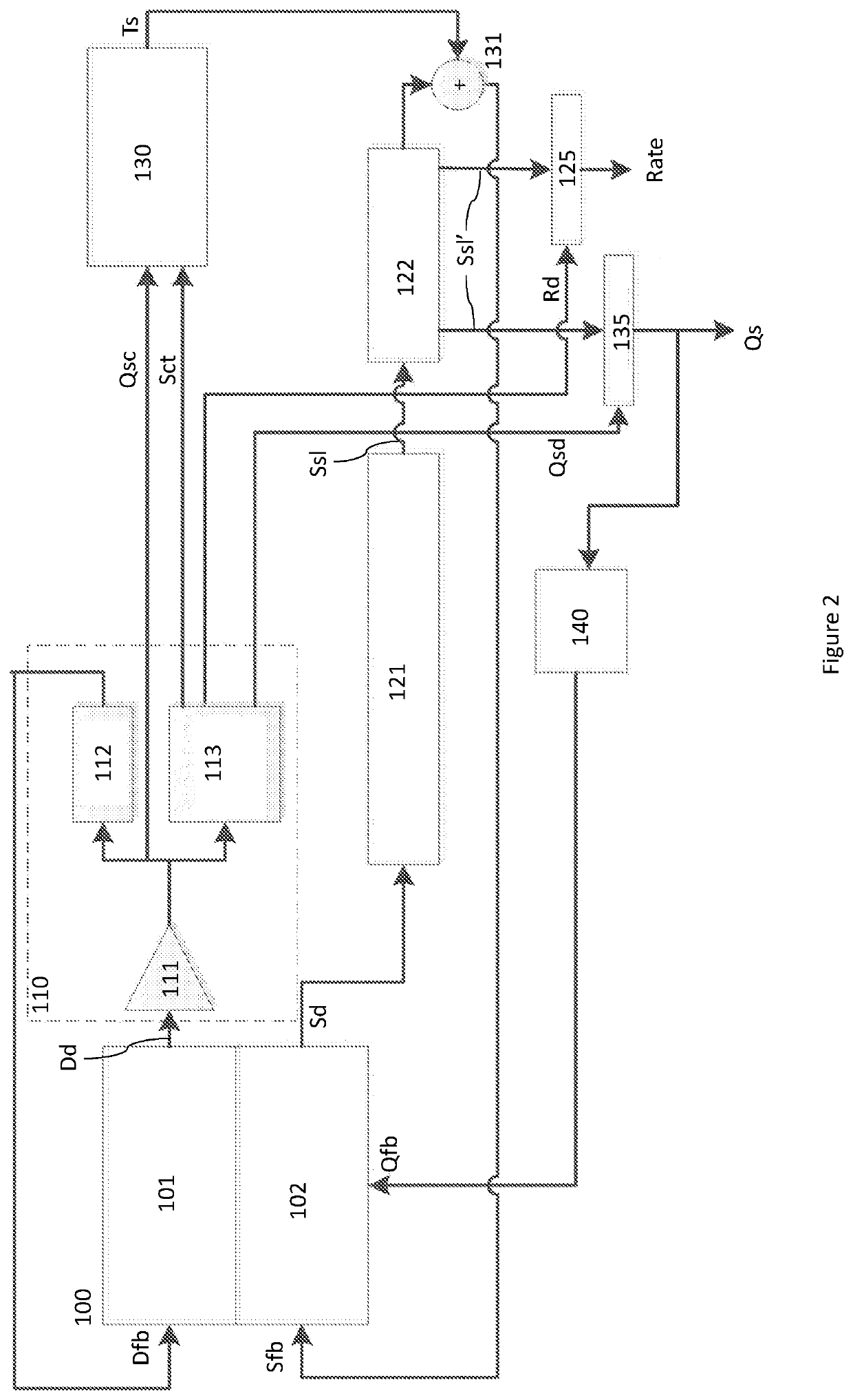
[0049]FIG. 2 illustrates a second embodiment which is similar to that of FIG. 1, but which has further been provided with a quadrature correction circuitry (140) that is configured to generate a quadrature feedback signal (Qfb) that may be fed towards the secondary resonator of the sensor element. Frequency response function of the quadrature feedback loop is preferably limited to the wanted Rate signal frequency band or below the wanted Rate signal frequency band so that the quadrature feedback loop frequency band effectively excludes the test signal frequency band by means of the quadrature correction circuitry (140) and / or the quadrature feedback electrodes feeding the quadrature feedback signal (Qfb) back towards the sense element (102). Quadrature correction circuitry and feedback are well known in the art.

[0050]In both embodiments, the self-test information that is exclusively obtained from the quadrature signal (Qs), any external angular rate signals, which are configured to ...


PUM


Abstract

A microelectromechanical gyroscope includes a drive loop having a drive element and a drive loop circuitry. The drive loop circuitry includes a clock generating circuitry for generating from the quadrature-phase detection signal a test clock signal, an angular rate phase demodulation signal and a quadrature phase demodulation signal. A sense loop includes a sense element and sense loop circuitry for detecting angular rate and producing a force-feedback signal. A test signal generator receives a quadrature-phase detection signal to be used as a quadrature-phase carrier signal and the test clock signal A summing element sums a test signal with the force-feedback signal to form a sense feedback signal. A rate phase demodulator produces a rate signal by demodulating a sense signal received from the sense loop with the angular rate phase demodulation signal, and a quadrature-phase demodulator produces a quadrature-phase output signal.

Description

FIELD[0001]The present invention relates to microelectromechanical devices and specifically to an inertial sensor with continuous self-test capability and a continuous self-test method for an inertial sensor.BACKGROUND[0002]Micro-Electro-Mechanical Systems or MEMS can be defined as micro-scale mechanical and electro-mechanical systems where at least some elements have a mechanical functionality. MEMS structures can be applied to quickly and accurately detect very small changes in physical properties.[0003]Motion can be considered to have six degrees of freedom: translations in three orthogonal directions and rotations around three orthogonal axes. The latter three may be measured by an angular rate sensor, also known as a gyroscope. MEMS gyroscopes use the Coriolis Effect to measure the angular rate. When a mass is moving in one direction and rotational angular velocity is applied, the mass experiences a force in orthogonal direction as a result of the Coriolis force. The resulting ...

Claims


Application Information

Patent Timeline
Patent Type & Authority Applications(United States)
IPC IPC(8): G01C19/5712G01C19/5776
CPCG01C19/5712G01C19/5776G01C25/005
Inventor AALTONEN, LASSEERKKILÄ, JOUNI
Owner MURATA MFG CO LTD
Why Eureka
Try Eureka