Supercharge Your Innovation With Domain-Expert AI Agents!

Electrode and percutaneous lead and method of use

a technology of electrodes and percutaneous leads, applied in the field of implantable pulse generators, can solve the problems of affecting functional ability, unable to depolarize the targeted neurons, and disrupting the perception of pain

Pending Publication Date: 2021-01-07
WAVEGATE CORP
View PDF11 Cites 1 Cited by
  • Summary
  • Abstract
  • Description
  • Claims
  • Application Information

AI Technical Summary

Benefits of technology

The present invention relates to an improved implantable pulse generator (IPG) and header combination for using optical reflectometry in spinal cord stimulation (SCS). The technical effect of this invention is to provide better pain relief and improved functional ability for patients with chronic pain by effectively treating pain through spinal cord stimulation. The invention also includes the use of percutaneous leads or surgical leads for spinal cord stimulation, as well as the placement of an electrode array for spinal cord stimulation in the epidural space between the dura and the walls of the spinal canal.

Problems solved by technology

Functional ability may be severely impacted by pain, which often is refractory to pharmacological and surgical treatment.
The resulting electric field disrupts the perception of pain.
Applying inadequate current will fail to depolarize the targeted neurons, rendering the treatment ineffective.
One challenge to subcutaneous IPG implants is the long-term survival of the IPG in the harsh in vivo environment.
Functional and mechanical degradation may occur with the ingress of body fluids.
Proteins common in the blood and interstitial fluid are known to bind to metallic ions, leading to corrosion.
Some materials can trigger an immune response and potentially a change in the local pH balance of the implantation site.
Specialized polymers and epoxies can avoid some of these problems, but often exhibit unacceptably high levels of cytotoxicity.
Similarly, another challenge to subcutaneous IPG implants is the tendency for the surrounding tissue to degrade around the IPG due to increased pressure the IPG edges place on the tissue.
Erosion of the device through the skin can occur, typically at the corners of the device where there is a focal concentration of pressure, and requires revision surgery to replace the device.
Another challenge to implementation of optical reflectometry for adaptive spinal cord stimulation is that leads coupled imprecisely to the IPG header are susceptible to movement which interferes with the stability of the optical signal.
Unstable optical signals result in undesirable signal-to-noise ratio which results in errors in delivered current and imprecise stimulation.
Yet another challenge to subcutaneous IPG implants is the extended recharge times. IPGs including a rechargeable battery must be periodically recharged.
However, during recharging, eddy currents are produced in the IPG casing causing temperature increase.
To maintain an acceptable temperature, charging duty cycles are typically shorter than ideal, thereby increasing the time required for recharging.
However, Tziviskos does not describe how to effectively connect or secure electrical leads or optical fibers.
However, Weinberg does not describe any design feature that reduces device erosion, nor does it disclose how to couple electrical leads or optical fibers to the implant.
However, Malinowski does not disclose the use of optics in the design to achieve proper pulse strength.
Deficiencies exist in the prior art related to the accuracy of lead coupling when using optical reflectometry for spinal cord stimulation.

Method used


Image

  • Electrode and percutaneous lead and method of use
  • Electrode and percutaneous lead and method of use
  • Electrode and percutaneous lead and method of use

Examples


Embodiment Construction

[0085]In the description that follows, like parts are marked throughout the specification and figures with the same numerals, respectively. The figures are not necessarily drawn to scale and may be shown in exaggerated or generalized form in the interest of clarity and conciseness.

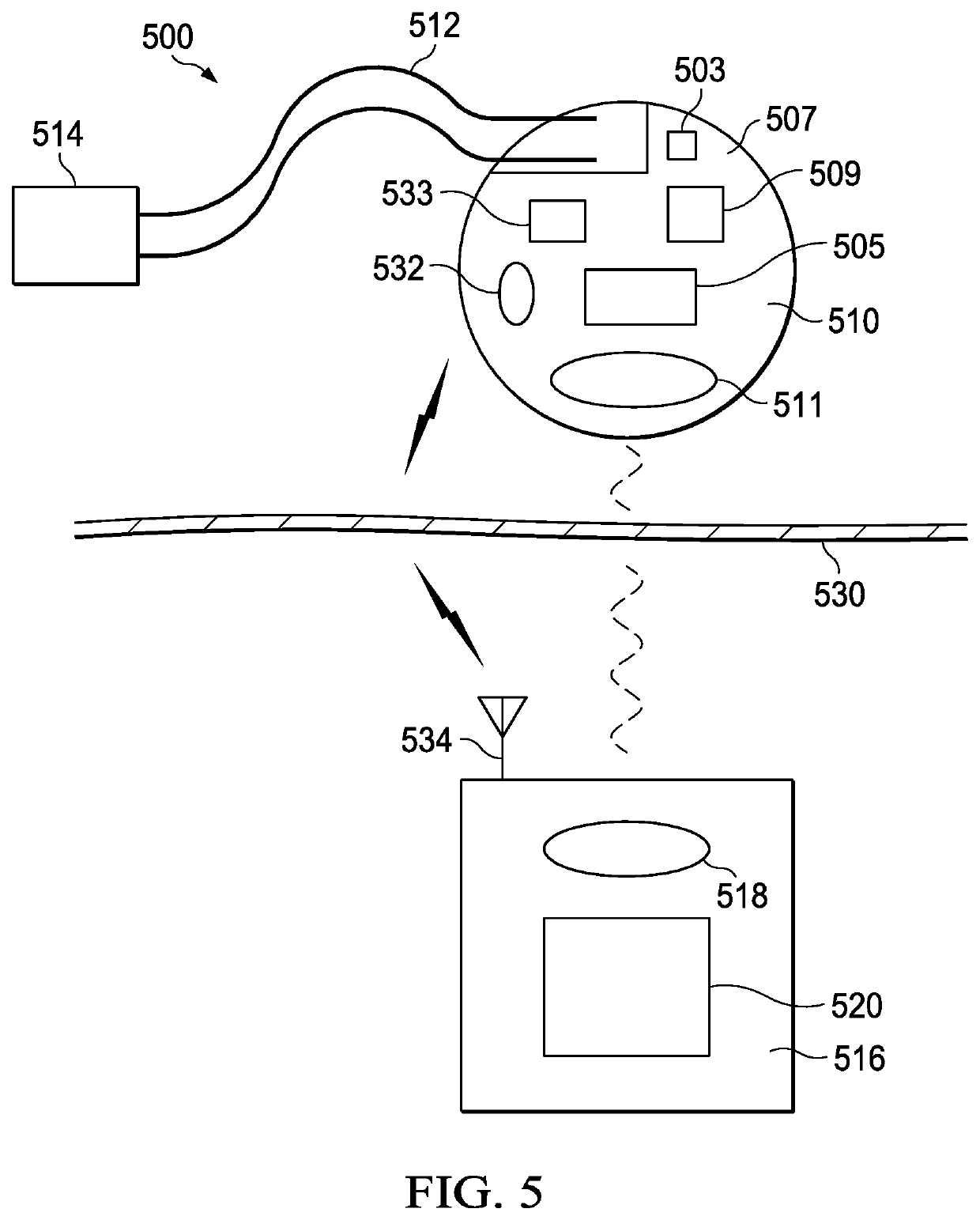
[0086]Referring then to FIG. 5, IPG charging and communication system 500 comprises an IPG device 510 implanted subcutaneously beneath skin surface 530.

[0087]IPG device 510 comprises an external non-metallic case 507 which facilitates transmission of charging and communication signals, with external system manager 516, as will be further described.

[0088]IPG device 510 further comprises main processor 505, operatively connected to signal processor 509. Main processor 505 is further operatively connected to secondary coil 511 and RF antenna 532, as will be further described.

[0089]Signal processor 509 is operatively connected to optoelectrical devices 503, as will be further described.

[0090]Optoelectrical dev...


PUM


Abstract

A percutaneous lead is provided which includes a generally tubular, multi-duct, flexible lead body. The lead body supports a distal set of electrodes and a proximal set of contacts which are connected by conductors in the ducts. The lead body further houses an optical fiber with a side firing section. The side firing section is held adjacent an optical transmission window, integrally formed with the flexible lead body. A cylindrical ferrule is provided to position the fiber in the header of an IPG.

Description

CROSS-REFERENCE TO RELATED APPLICATIONS[0001]This application is a continuation of U.S. application Ser. No. 16 / 946,715 filed on Jul. 1, 2020, which is a continuation of U.S. application Ser. No. 16 / 946,714 filed on Jul. 1, 2020. This application claims priority benefits from U.S. Provisional Application No. 62 / 869,372 filed on Jul. 1, 2019; U.S. Provisional Application No. 62 / 869,377 filed on Jul. 1, 2019 and U.S. Provisional Application No. 62 / 869,391 filed on Jul. 1, 2019. The patent applications identified above are incorporated herein by reference in its entirety to provide continuity of disclosure.FIELD OF THE INVENTION[0002]The present invention relates to an improved implantable pulse generator (IPG) and header combination for using optical reflectometry in spinal cord stimulation (SCS).BACKGROUND OF THE INVENTION[0003]Chronic pain may arise from a variety of conditions, most notably from nerve injury as in the case of neuropathic pain, or from chronic stimulation of mechani...

Claims


Application Information

Patent Timeline
Patent Type & Authority Applications(United States)
IPC IPC(8): A61N1/375A61N1/36A61N1/378H02J7/02H02J50/10G02B6/42G02B6/36
CPCA61N1/3752A61N1/36071A61N1/36139G02B6/3624H02J7/02H02J50/10G02B6/4246A61N1/3787H01R4/30G02B6/4293H02J7/00034H02J50/80A61N1/0551H02J2310/23A61N1/0553A61N1/37518G02B6/02033A61N1/0558A61N1/378G02B6/4212G02B6/4234H01R13/08A61N1/37223
Inventor WOLF, II, ERICH W.
Owner WAVEGATE CORP
Features
  • R&D
  • Intellectual Property
  • Life Sciences
  • Materials
  • Tech Scout
  • Unparalleled Data Quality
  • Higher Quality Content
  • 60% Fewer Hallucinations
Learn More