Organic sludge treatment device and treatment method

a treatment device and organic sludge technology, applied in the direction of energy-based wastewater treatment, drying machines with non-progressive movements, drying machines, etc., can solve the problems of cement production efficiency and clinker production amount decline, cement production efficiency increase, etc., to improve the handleability of organic sludge, stable vaporization for a short time, and high viscosity

Active Publication Date: 2021-01-14
TAIHEIYO ENG +1
View PDF4 Cites 0 Cited by
  • Summary
  • Abstract
  • Description
  • Claims
  • Application Information

AI Technical Summary

Benefits of technology

[0028]Further, mixing ratio of the organic sludge and the fractionated preheated raw material may be set to be the organic sludge (solid content whose moisture is removed): the fractionated preheated raw material=1:3-1:40. With this, moisture can stably be vaporized for a short time. Moreover, diluting combustibles of an organic sludge with a fractionated preheated raw material as a noncombustible solves apprehension of dust explosion. Still further, the above mixing ratio remarkably improves handleability of an organic sludge with high viscosity.
[0029]Setting calcium oxide (CaO) content of the preheated raw material less or equal to 20 mass % avoids difficult control and large heat loss.
[0030]As described above, with the present invention, it becomes possible to safely treat organic sludge while minimizing facility costs, cement production efficiently and reduction in clinker production amount.

Problems solved by technology

However, in the technique described in the patent document 5, facility cost increases since the flash dryer and so on are required, and when an exhaust gas of the flash dryer is returned to a cement burning device to perform odor treatment of the gas, cement production efficiency and clinker production amount decrease.

Method used


Image

  • Organic sludge treatment device and treatment method

Examples


Embodiment Construction

[0032]Next, an embodiment of the present invention will be explained with referenced to the drawing in detail.

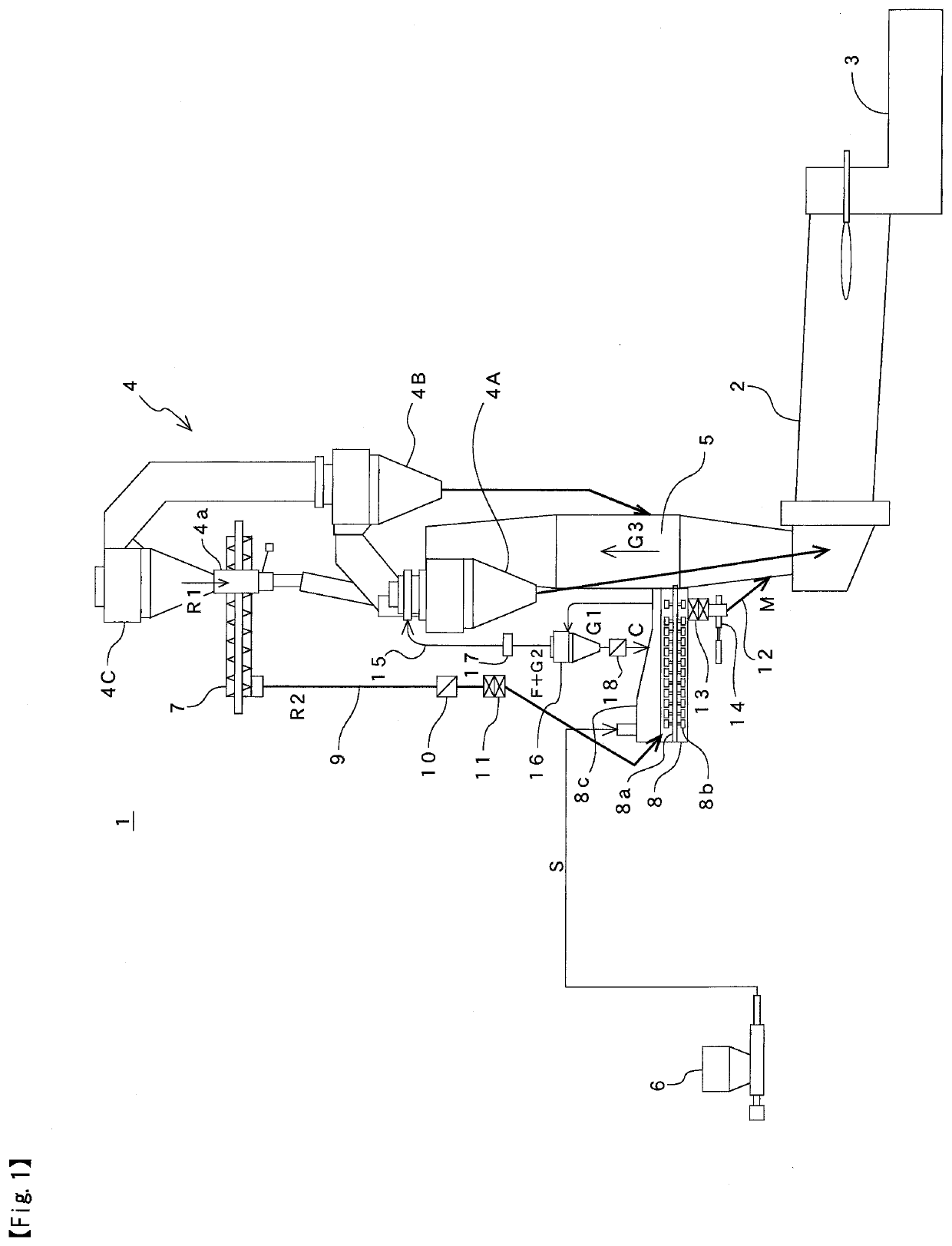
[0033]FIG. 1 shows a cement burning device with an organic sludge treatment device according to the present invention, and the cement burning device 1 is, in addition to components of a common cement burning device such as a cement kiln 2, a clinker cooler 3, a preheater 4 and a calciner furnace 5, provided with: a fractionation device 7 for fractionating a part of a cement raw material R1 discharged from a raw material chute 4a of the third cyclone 4C of the preheater 4; a mixing device 8 for mixing the fractionated preheated raw material R2 with an organic sludge S supplied from an organic sludge supply device 6 to dry the organic sludge S; and so on. Although the preheater 4 includes four or five stage cyclones, illustration of devices above the third cyclone 4C is omitted in FIG. 1. The organic sludge S is sewage sludge, papermaking sludge, building pit sludge, food slud...


PUM

PropertyMeasurementUnit
temperatureaaaaaaaaaa

Abstract

To treat organic sludge while keeping facility costs, cement production efficiency, and a reduction in clinker production amount to a minimum. An organic sludge treatment device includes: a fractionation device 7 that fractionates a preheated raw material R2 from a preheater cyclone 4C excluding a bottommost cyclone of a cement burning device 1; a mixing device 8 that mixes an organic sludge S with the fractionated preheated raw material, and that dries the organic sludge using sensible heat of the preheated raw material; and a supply device (mixture chute 12, double-flap damper 13, shut damper 14) that supplies a mixture M from the mixing device to a calciner furnace 5 of the cement burning device or to a duct disposed between a kiln inlet portion of a cement kiln 2 and the calciner furnace. The treatment device may be provided with an introduction device for introducing an exhaust gas G2 including dust, odor and water vapor from the mixing device to a gas outlet of a bottommost cyclone 4A of the cement burning device.

Description

CROSS-REFERENCE TO RELATED APPLICATIONS[0001]The present application claims priority to International Application No. PCT / JP2019 / 010030 filed of Mar. 12, 2019 and International Application No. PCT / JP2018 / 014386 filed on Apr. 4, 2018, the disclosures of which are incorporated herein by reference.STATEMENT RE: FEDERALLY SPONSORED RESEARCH / DEVELOPMENT[0002]Not ApplicableBACKGROUND1. Technical Field of the Invention[0003]The present invention relates to a treatment device and a treatment method for organic sludge such as sewage sludge, and more particularly to a device and so on for effectively utilizing organic sludge as fuel and the like.2. Description of the Related Art[0004]In recent years, it has been difficult to perform conventional landfill treatment of organic sludge such as sewage sludge discharged from sewage treatment plants in view of depletion of landfill and prevention of environmental pollution. Then, various methods of effectively utilizing sewage sludge and the like as...

Claims


Application Information

Patent Timeline
Patent Type & Authority Applications(United States)
IPC IPC(8): C02F11/06C02F11/13C04B7/40C04B7/44C04B7/42C10L5/46F26B17/20F27B7/32
CPCC02F11/06C10L2290/24C04B7/40C04B7/4423C04B7/4438C04B7/428C10L5/46F26B17/20F27B7/32C02F2303/02C02F2303/10C04B2290/20C10L2290/08C10L2290/141C02F11/13B01D45/12F27D13/00F27D3/00Y02E50/10Y02W10/40C04B7/4407C10L2290/06C10L2290/02C10L9/10F27B7/3205F26B11/16C02F2103/12C04B7/4446Y02W10/30C02F11/00
Inventor YAMAMOTO, YASUSHIKIMURA, TAKAYUKIKAMADA, KOUJIIZUMI, KAZUSHIUENO, NAOKI
Owner TAIHEIYO ENG
Why Eureka
Try Eureka