Process for the Manufacture of Trifluoroethylamine

a technology of trifluoroethylamine and manufacturing process, which is applied in the preparation of halogenated hydrocarbons, physical/chemical process catalysts, hydrogen halide split-off, etc., can solve the problems of high energy demand, reduce simplify the process, and avoid time and energy consumption. , the effect of reducing the number of separation steps

Active Publication Date: 2021-01-21
FUJIAN YONGJING TECH CO LTD
View PDF0 Cites 0 Cited by
  • Summary
  • Abstract
  • Description
  • Claims
  • Application Information

AI Technical Summary

Benefits of technology

[0040]A very particular advantage of the present invention employing a microreactor, or a continuous flow reactor with the before said lateral dimensions, the number of separating steps can be reduced and simplified, and may be devoid of time and energy consuming, e.g. intermediate, distillation steps. Especially, it is a particular advantage of the present invention employing a microreactor, or a continuous flow reactor with the before said lateral dimensions, that for separating simply phase separation methods can be employed, and the non-consumed reaction components may be recycled into the process, or otherwise be used as a product itself, as applicable or desired.
[0041]In addition to the preferred embodiments of the present invention using a microreactor in steps (d) and (e), as defined herein and in the claims, in the processes according to the invention, in addition or alternatively to using a microreactor, it is also possible to use in steps (d) and (e) to employ a plug flow reactor or a tubular flow reactor, respectively.
[0042]Plug flow reactor or tubular flow reactor, respectively, and their operation conditions, are well known to those skilled in the field.
[0043]Although the use of a continuous flow reactor with upper lateral dimensions of about ≤5 mm, or of about ≤4 mm, and in particular of a microreactor, is particularly preferred in the present invention, depending on the circumstances, it could be imagined that somebody dispenses with an microreactor, then of course with yield losses and higher residence time, higher temperature, and instead takes a plug flow reactor or turbulent flow reactor, respectively. However, this could have a potential advantage, taking note of the mentioned possibly disadvantageous yield losses, namely the advantage that the probability of possible blockages (tar particle formation by non-ideal driving style) could be reduced because the diameters of the tubes or channels of a plug flow reactor are greater than those of a microreactor.
[0044]The possibly allegeable disadvantage of this variant using a plug flow reactor or a tubular flow reactor, however, may also be seen only as subjective point of view, but on the other hand under certain process constraints in a region or at a production facility may still be appropriate, and loss of yields be considered of less importance or even being acceptable in view of other advantages or avoidance of constraints.
[0045]In the following, the invention is more particularly described in the context of using a microreactor. Preferentially, a microreactor used according to the invention is a ceramic continuous flow reactor, more preferably a SiC (silicon carbide) continuous flow reactor, and can be used for material production at a multi-to scale. Within integrated heat exchangers and SiC materials of construction, it gives optimal control of challenging flow chemistry application. The compact, modular construction of the flow production reactor enables, advantageously for: long term flexibility towards different process types; access to a range of production volumes (5 to 400 l / h); intensified chemical production where space is limited; unrivalled chemical compatibility and thermal control.

Problems solved by technology

HCFC-133a (1,1,1-trifluoro-2-chloroethane (HCFC-133a) is already used industrially for producing as a precursor to the refrigerant 134a in a gas-phase reaction at a temperature of about 300° C. A disadvantage of a gas-phase reaction (even if the chemistry works well) is, of course, the high energy demand.

Method used


Image

  • Process for the Manufacture of Trifluoroethylamine
  • Process for the Manufacture of Trifluoroethylamine
  • Process for the Manufacture of Trifluoroethylamine

Examples


example 1

Pre-Fluorination Procedure in Autoclave:

[0115]

[0116]In a 250 ml autocalve (high grade stainless steel 1.4571, Roth company, 1 deep pipe made out of plastics, 1 outlet over gas phase) with HDPTFE Inliner and magnetic stirrer, 36.78 g (0.123 mol) SbCl5 are placed, the autoclave is closed and a 20 fold molar excess of HF (waterfree) (2.46 mol, 49.22 g) is fed from a HF cylinder's liquid phase (cylinder has to be pressurized before with N2) into the autoclave. Even if pressure in the autoclave raises already immediately through the formed HCl in the autoclave after contact with HF, the autoclave is stirred with said magnetic stirrer and heated in an oil bath or electrical heater for 3 h to 100° C. to get an almost complete exchange of Chlorine atoms by fluorine atoms. The pressure on the autoclave is very carefully OVER THE GAS PHASE exit of the autoclave released after cooling down of the autoclave to room temperature to atmospheric pressure into a (just water containing) scrubber (the...

example 2

Fluorination Step in (Batch) Autoclave:

[0117]

[0118]100.0 g (4,998 mol) fresh HF were added into the autoclave over the deep pipe at room temperature, then 62.14 g (0.473 mol) Trichloroethylen (TCE) were dosed with an HPLC pump over the deep pipe into the autoclave (also at room temperature), pressure will start to raise. The autoclave is heated in an oil bath or electrically to 100° C. for 1 h (better 2 h). The pressure will rise constantly. Afterwards, after cooling to room temperature, the pressure is slowly and very carefully released OVER THE GAS PHASE exit of the autoclave to atmospheric pressure into a scrubber with fresh ice water (work up step 1, not with the scrubber water already used for the pre-fluorination), a 2nd phase will be optionally formed already, especially during the end of pressure release. Now the autoclave either is pressurized again over the gas phase inlet of the autoclave with N2 pressure and the remaining content in the autoclave is carefully fed into th...

example 3

Continuous Example Connected with Amination Step
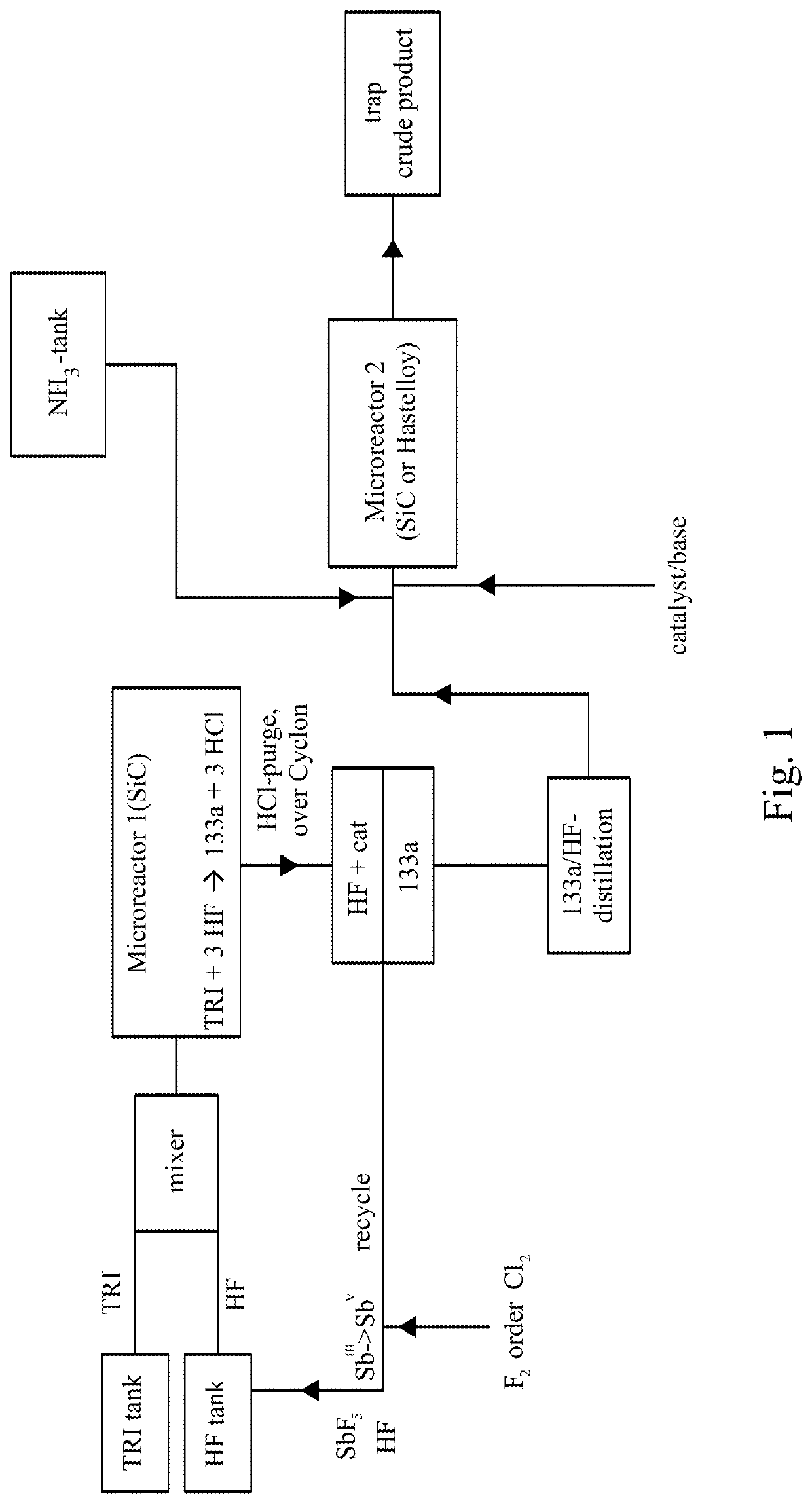
Fluorination Step:

[0119]TRI was fed out of a storage tank together with HF (molar ration TRI / HF=1:9) containing 10 mol % SbF5 (prepared according to the pre-fluorination procedure in batch) into a ChemtrixMicroreactor (27 ml) made out of SiC heated to 110° C., feed is controlled over a process control system securing a residence time of 200 seconds. A cylon, where a pressure valve is keeping 20 bar pressure, is used after the microreactor to remove some HCl before the mixture goes into a settler to separate organic phase with the 133a and a HF phase containing the catalyst and some HCl. The organic phase is subjected to a pressure distillation to get pure (HF free) 133a. There is a storage (or puffer) tank after the 133a distillation.

Amination Step (NH3 as Cl-Scavenger):

[0120]133a is fed together with liquid NH3 into a 2nd microreactor. This reactor can be out of stainless steel or also SiC (volume 27 ml). This reactor is heated to 190...


PUM

PropertyMeasurementUnit
flow rateaaaaaaaaaa
temperatureaaaaaaaaaa
pressureaaaaaaaaaa

Abstract

The invention relates to a new process for the manufacture of fluoroaryl compounds and derivatives thereof, in particular of fluorobenzenes and derivatives thereof, and especially wherein said manufacture relates to an environmentally friendly production of the said compounds. Thus, the present invention overcomes the disadvantages of the prior art processes, and in a surprisingly simple and beneficial manner, and as compared to the prior art processes, in particular, the invention provides a more efficient and energy saving processes, and also provides a more environmentally friendly process, for the manufacture of nuclear fluorinated aromatics, and preferably of nuclear fluorinated fluorobenzenes. Accordingly, in one aspect of the invention, an industrially beneficial process for preparing fluorobenzenes from halobenzene precursors using HF to form hydrogen halide is provided by the present invention. A beneficial and surprisingly simple use of chlorobenzene as an industrially interesting starting material in the manufacture of fluorobenzene is provided.

Description

BACKGROUND OF THE INVENTIONField of the Disclosure[0001]The invention relates to a process for the manufacture of trifluoroethylamine (TFEA).Description of Related Art[0002]All prior art processes for the manufacture of HCFC-133a (1,1,1-trifluoro-2-chloroethane (HCFC-133a) are based on PER (tetrachloroethylene) or TRI (trichloroethylene) as starting materials and are performed in gas-phase reactions.[0003]Furthermore, the following two-step production methods for HCFC-133a (CF3CH2Cl, the most important intermediate in production of HFC-134a; CF3—CH2F) are known in conventional batch or continuous reactors from the International patent application WO 2000 / 076945 A2 (Braun et al.), and the Chinese patent application CN 103102241 A (Yang Huimin).[0004]Herein, the WO 2000 / 076945 A2 discloses a method of UV-activated chlorination, whereby alkanes containing chlorine can be produced by attaching chlorine to C—C-double bonds or C—C-triple bonds or by exchanging hydrogen for chlorine, by br...

Claims


Application Information

Patent Timeline
Patent Type & Authority Applications(United States)
IPC IPC(8): C07C209/08C07C211/15
CPCC07C209/08B01J27/06C07C211/15C07C17/087C07C17/25B01J19/0093C07C19/12C07C21/18C07C17/21
Inventor DU, HONGJUNWU, WENTING
Owner FUJIAN YONGJING TECH CO LTD
Why Eureka
Try Eureka