Electromagnet control device and electromagnet system

a control device and electromagnet technology, applied in the direction of electromagnets without armatures, magnetic gradient measurements, instruments, etc., can solve the problem of difficult fine adjustment of plasma density distribution, and achieve the effect of reducing the load relating to computation in the electromagnet control devi

Active Publication Date: 2021-03-04
EBARA CORP
View PDF0 Cites 3 Cited by
  • Summary
  • Abstract
  • Description
  • Claims
  • Application Information

AI Technical Summary

Benefits of technology

[0028]According to a third mode of the present invention, the third mode comprises the first mode, wherein the first function, the second function, and the third function are functions representing relationship between magnetic flux density and current. According to the above mode, current that is made to flow through the coil can be determined directly from a desired magnetic flux density, without necessity of conversion to another parameter. Thus, load relating to computation in the electromagnet control device can be reduced.
[0029]According to a fourth mode of the present invention, an electromagnet system comprising the electromagnet control device according to the first mode and the electromagnet is provided. According to the above electromagnet system, effect similar to that obtainable from the first mode can be obtained.

Problems solved by technology

In the method in which a permanent magnet is mechanically moved, it is difficult to finely adjust plasma density distribution, since strength of the magnetic field generated by the permanent magnet is fixed.

Method used


Image

  • Electromagnet control device and electromagnet system
  • Electromagnet control device and electromagnet system
  • Electromagnet control device and electromagnet system

Examples


first embodiment

A. First Embodiment

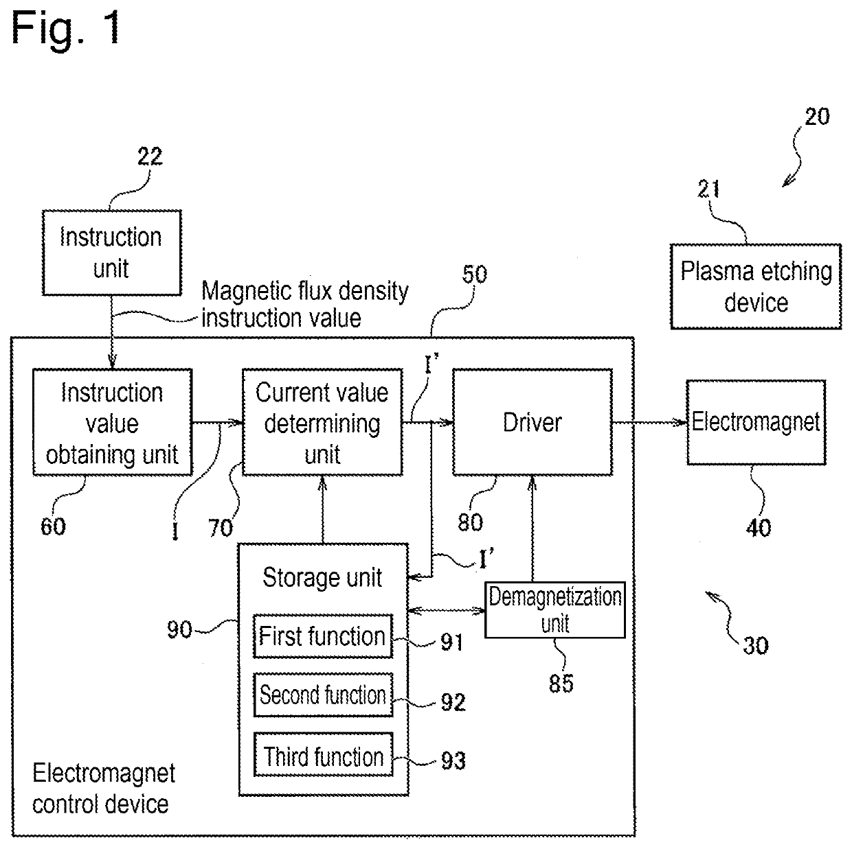
[0049]FIG. 1 is a block diagram which schematically shows a construction of a plasma processing system 20 which is selected as an embodiment of the present invention. In the present embodiment, the plasma processing system 20 is a system for performing plasma etching, and used for etching a substrate (for example, a wafer) in a semiconductor manufacturing process, for example. As shown in FIG. 1, the plasma processing system 20 comprises a plasma etching device 21, an instruction unit 22, and an electromagnet system 30. The plasma etching device 21 comprises a chamber (a graphic representation thereof is abbreviated). Plasma is generated in the chamber, and an object of processing is etched by ions or radicals generated thereby. In the present embodiment, the instruction unit 22 is a personal computer, and connected to the electromagnet system 30 (more specifically, an electromagnet control device 50 which will be explained later) to allow communication between th...


PUM

PropertyMeasurementUnit
magnetic flux densityaaaaaaaaaa
magnetic flux densitiesaaaaaaaaaa

Abstract

A target value of magnetic flux density and magnetic flux density actually obtained are made to coincide precisely with each other. An electromagnet control device comprises a current value determining unit for determining, based on a magnetic flux density instruction value, a value of current that is made to flow through a coil. The current value determining unit is constructed to execute a second process for determining, based on a second function, a value of the current, if the magnetic flux density is to be decreased from that in a first magnetization state, and a fourth process for expanding or reducing the second function by use of a first scaling ratio for transforming it to a fourth function, and determining, based on the fourth function obtained after above transformation, a value of the current, if the magnetic flux density is to be decreased from that in a third magnetization state.

Description

TECHNICAL FIELD[0001]The present invention relates to the technique for controlling current flowing through a coil of an electromagnet comprising a yoke and the coil.BACKGROUND ART[0002]In a plasma processing device (for example, a plasma etching device and so on) in prior art, an etching method using magnetron discharge has been developed to be practically used. The above method is that for efficiently etching a surface of a wafer, in a chamber into which an etching gas is introduced, by applying an electric field in a direction and a magnetic field in another direction that are orthogonal to each other, and using drift motion of electrons that occurs when the above fields are applied.[0003]In such an etching device, for controlling distribution of plasma density in a chamber, the generated magnetic field is controlled by a magnet positioned outside the chamber. Regarding methods for controlling magnetic fields, a method in which a permanent magnet is mechanically moved and a metho...

Claims


Application Information

Patent Timeline
Patent Type & Authority Applications(United States)
IPC IPC(8): G01R33/022G01R33/028
CPCG01R33/022G01R33/0283H01F7/064H01J37/3266H01J37/32669H01J37/3299H01J37/32926H01J37/3464H01F7/20
Inventor TAKEUCHI, HARUKAOHASHI, TOMONORISATO, ICHIJU
Owner EBARA CORP
Why Eureka
Try Eureka