

Optical radar apparatus
a radar and optical technology, applied in the field of optical radar apparatus, can solve the problems of reduced signal intensity, reduced polarization, high cost of scanning type, etc., and achieve the effect of improving the sn ratio of ligh
- Summary
- Abstract
- Description
- Claims
- Application Information
AI Technical Summary
Benefits of technology
Problems solved by technology
Method used
Image

Examples
embodiment 1
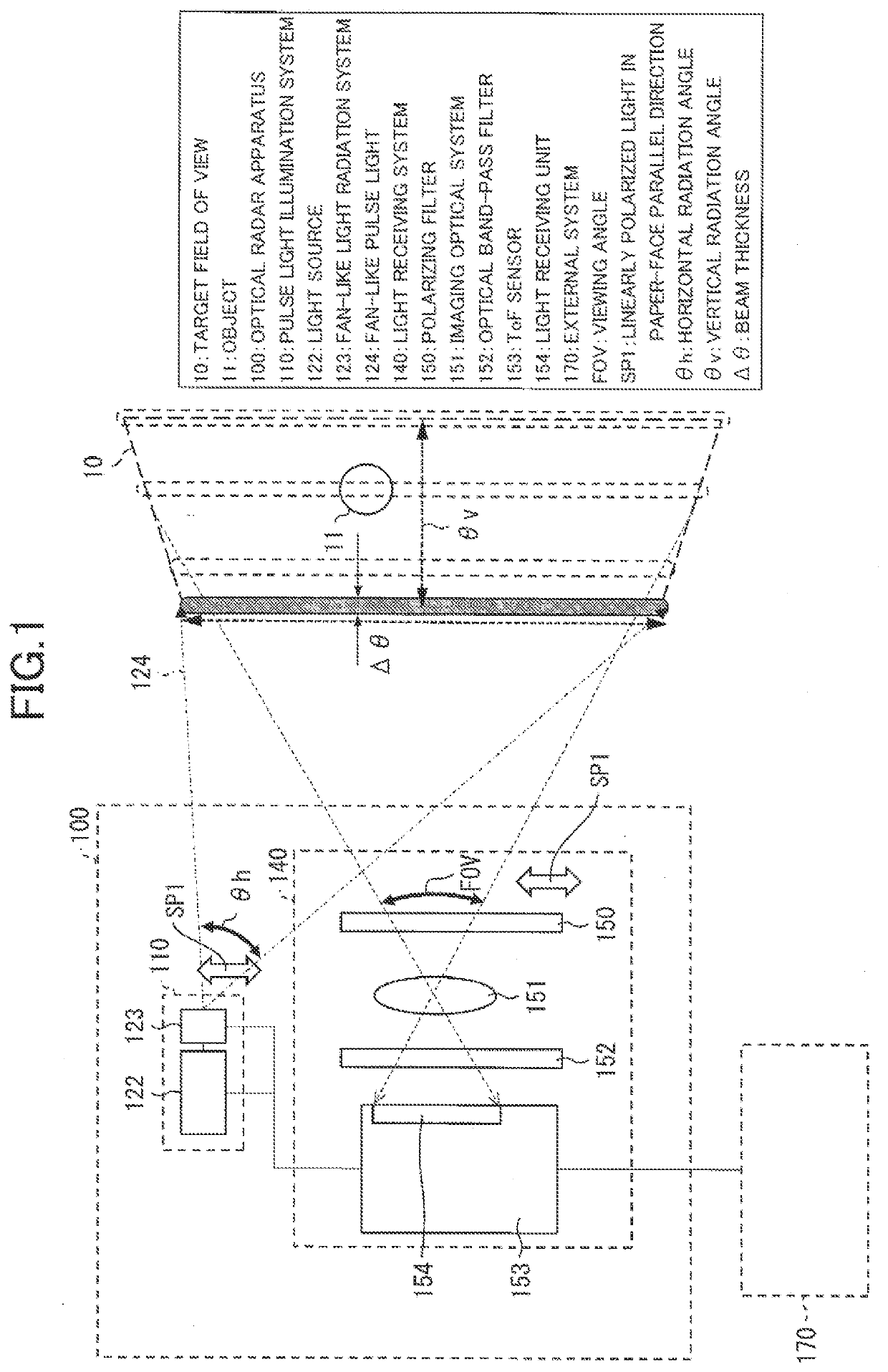
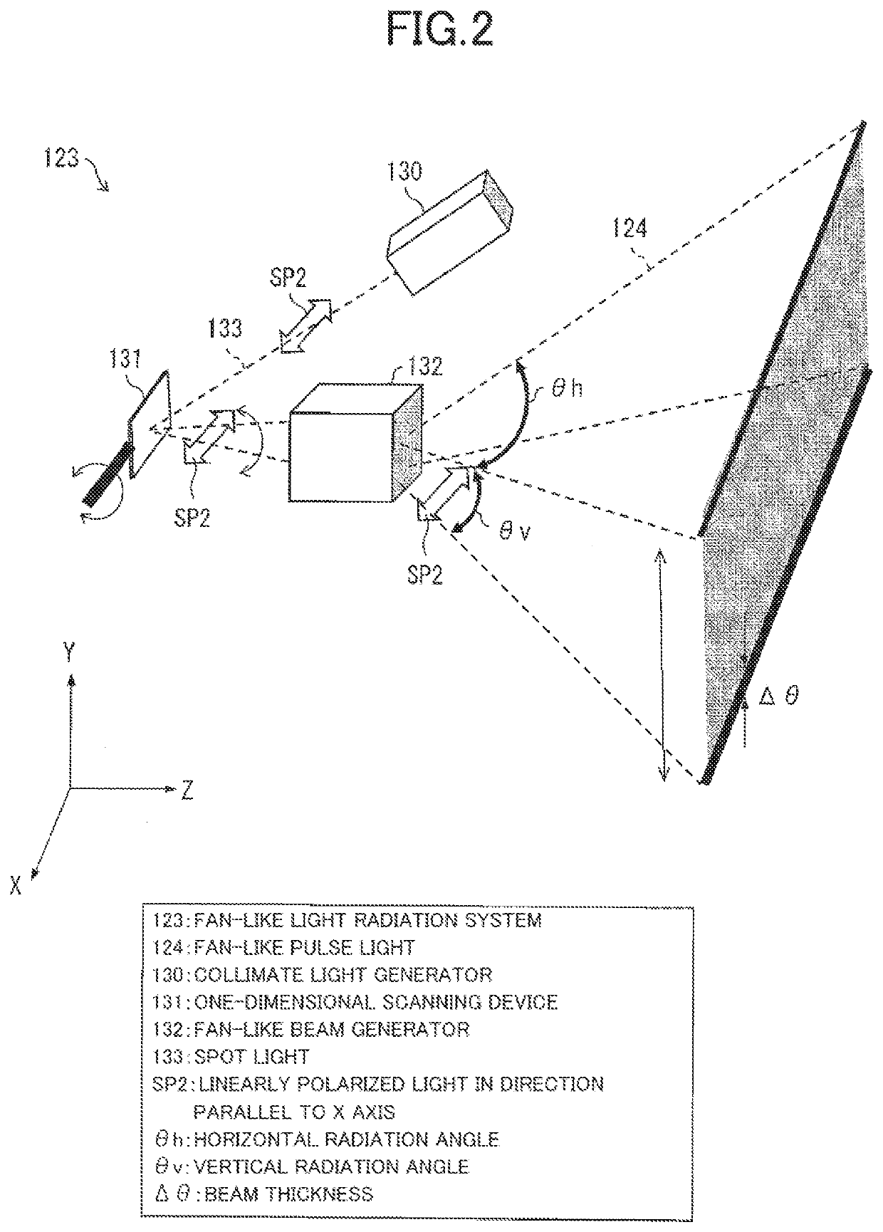
[0030]A configuration of an optical radar apparatus 100 according to Embodiment 1 of the invention will be described with reference to FIGS. 1 to 4. The optical radar apparatus 100 includes a light source 122 that emits pulse light, a one-dimensional scanning device 131 that performs scanning in one direction with the pulse light, a fan-shaped beam generator 132 that radiates the pulse light so as to be spread in a plane vertical to a plane that includes the direction of the scanning, a ToF sensor 153 that measures a distance to an object 11 by using reflection light from the object 11 irradiated with fan-shaped pulse light 124 that is obtained by the scanning and the radiation and is polarized in a direction vertical to the direction of the scanning, and a polarizing filter 150 that is arranged in a light path extending from the object 11 to a light receiving unit 154 of the ToF sensor 153 and allows transmission of the light polarized in the direction vertical to the direction of ...
embodiment 2
[0051]FIG. 5 is a schematic view illustrating a configuration of an optical radar apparatus 101 according to the present embodiment. FIG. 6 is a schematic view for explaining reflection light 211R that is interfering specular reflection light of sunlight 211 in the optical radar apparatus 101. The optical radar apparatus 101 of the present embodiment is different from the optical radar apparatus 100 of Embodiment 1 in terms of including two systems of a light receiving system 140a and a light receiving system 140b as illustrated in FIG. 5. The difference lies in that the light receiving system 140a has a polarizing filter 150a through which light that is polarized in the same direction as the polarization direction of the fan-shaped pule light 124 (refer to FIG. 1), in other words, light of the linearly polarized light SP1 in the paper-face parallel direction is transmitted, and that the light receiving system 140b has a polarizing filter (sub polarizing filter) 150b through which l...
embodiment 3
[0055]FIG. 7 is a schematic view illustrating a configuration of an optical radar apparatus 102 according to the present embodiment. The present embodiment aims to achieve the same effect as that of Embodiment 2 and the optical radar apparatus 102 is different from that of Embodiment 1 in that one system of a light receiving system 140c has a polarizing device 180 capable of changing a polarization direction as illustrated in FIG. 7. The light receiving system 140c is the same as the light receiving system 140 of the optical radar apparatus 100 in the other points.
[0056]The polarizing device 180 is able to be constituted by, for example, a polarizer through which light that is linearly polarized in one direction is transmitted and a rotation mechanism that mechanically rotates the polarizer. Alternatively, the polarizing device 180 may be a combination of a polarizer and a device that change the polarization direction by 90 degrees by applying a voltage like a liquid crystal polariz...
PUM
 Abstract
Description
Claims
Application Information