

Membrane electrode assembly with improved cohesion
a technology of membrane electrodes and components, applied in the direction of cell components, fuel cells, electrical equipment, etc., can solve the problems of fuel cell performance decline, carbon monoxide poisoning of anodes, and one of the most expensive components of fuel cells
- Summary
- Abstract
- Description
- Claims
- Application Information
AI Technical Summary
Benefits of technology
Problems solved by technology
Method used
Image

Examples
example 1
Test
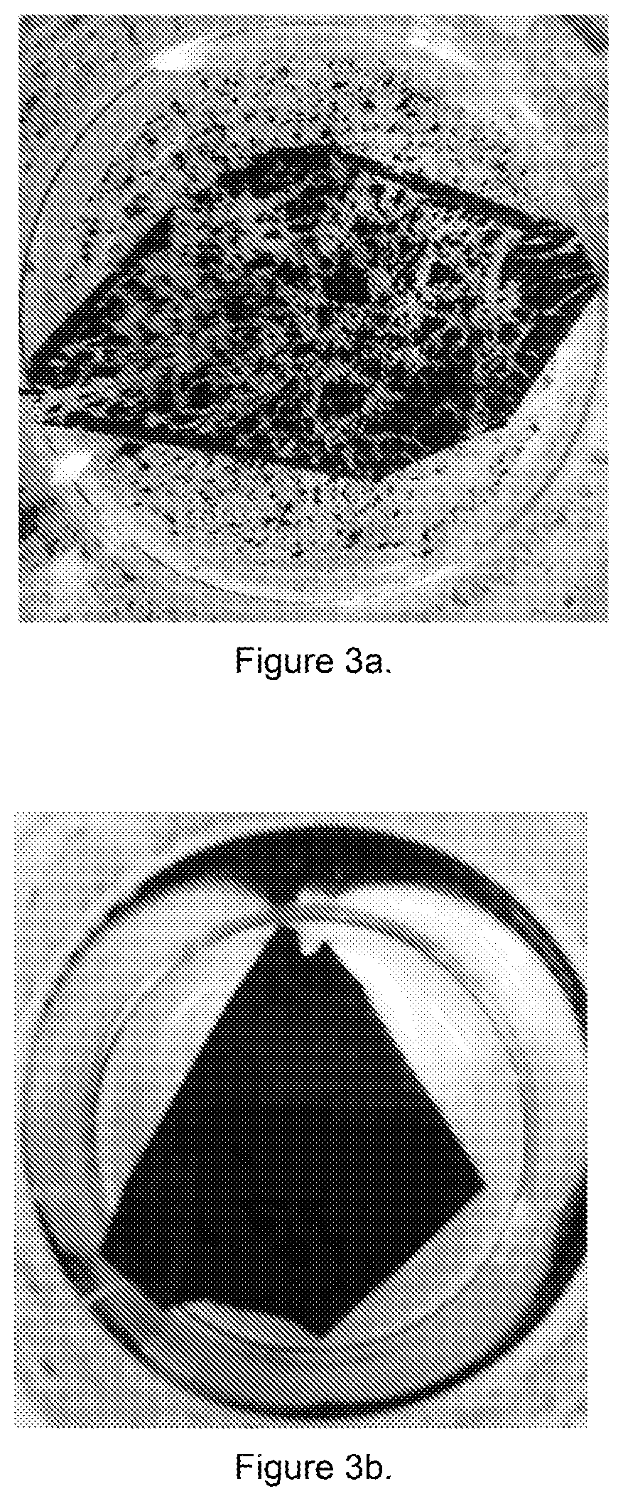
[0052]About 10 wt % of a representative PEO-PPO block co-polymer (Pluronic® F108 from Sigma-Aldrich) was mixed with 1100 EW Nafion® ionomer and stirred for one hour at room temperature. A catalyst having about 47 wt % platinum supported on a low surface area carbon support (TKK, Japan) was added to the mixture under stirring, followed by shear mixing for several minutes and then microfluidized to form a cathode catalyst ink. The cathode catalyst ink was then coated onto a Nafion® membrane (DuPont) and air dried for form a half catalyst-coated membrane. A control half catalyst-coated membrane was also made without the block co-polymer.
[0053]To test for adhesion properties, both half catalyst-coated membranes were immersed in 750 mL of water at about 80 degrees Celsius for about 2 to 6 hours. As shown in FIGS. 3a and 3b, the catalyst layer in the control half catalyst-coated membrane had flaked off after being immersed in hot water for only 2 hours (FIG. 3a) while catalyst layer i...
example 2
issolution
[0054]To determine the amount of block co-polymer that may dissolve out of the catalyst layer, two half catalyst-coated membranes were made with 10 wt % of the representative PEO-PPO block co-polymer using the method above (Example 1). One of the half catalyst-coated membranes was also annealed at about 150 degrees Celsius and compacted at 15 bar pressure for about 3 minutes to recreate decal transfer conditions of the catalyst layer to the membrane.
[0055]Both of the half catalyst-coated membranes were washed in water at about 75 degrees Celsius for about 6 hours and the liquid was analyzed for total organic carbon (TOC). It was then back calculated to determine the amount of washout of the PEO-PPO block co-polymer, which was about 60% for non-annealed sample and about 35% for annealed sample. Without being bound by theory, it is suspected that at least one of the annealing and compaction process decreased dissolution of the block co-polymer.
example 3
ng
[0056]Four MEAs with 45 cm2 active area were made with varying amounts of the representative PEO-PPO block co-polymer as described in Example 1 in the binder of the cathode catalyst layer (at 0 wt %, 2.5 wt %, 5 wt % and 10 wt %). The PEO-PPO block co-polymer was mixed with 1100 EW Nafion® ionomer and stirred for one hour at room temperature. A catalyst having 40 wt % platinum supported on a high surface area carbon support (TKK, Japan) was added to the mixture under stirring, followed by shear mixing for several minutes and then microfluidized to form a cathode catalyst ink. The cathode catalyst ink was then coated onto a reinforced perfluorosulfonic acid membrane (W.L. Gore & Associates). An anode catalyst ink having platinum supported on a high surface area carbon and 1100 EW Nafion® ionomer was coated onto a release sheet and decal transferred to the membrane at 150 degrees Celsius to form a catalyst-coated membrane. The anode and cathode catalyst loadings for all of the MEAs ...
PUM
| Property | Measurement | Unit |
|---|---|---|
| Molar mass | aaaaa | aaaaa |
| Molar mass | aaaaa | aaaaa |
| Temperature | aaaaa | aaaaa |
Abstract
Description
Claims
Application Information