Supporting member and supporting member assembly for implantation into or between subjects bones, and template plug and tamper corresponding to the same

a technology which is applied in the field of supporting member and supporting member assembly to be implanted into or between subjects bones, and a template plug and a tamper corresponding to the supporting member. it can solve the problems of multiple complications, time-consuming and time-consuming, and prone to massive blood loss

Pending Publication Date: 2021-06-24
HSIEH JUI YANG
View PDF15 Cites 0 Cited by
  • Summary
  • Abstract
  • Description
  • Claims
  • Application Information

AI Technical Summary

Benefits of technology

[0030]3. The present invention further provides a supporting member assembly that is formed by sequentially implanting and connecting a plurality of supporting members into a bone or between two connected bones so as to push outward the end plate(s) to be treated and thereby expand the collapsed fractured bone(s). This supporting member assembly is an improvement over the one-size implants used in the conventional implantation techniques on the grounds that an existing one-size implant cannot “be a single micro-unit before implantation into or between a subject's bones and c

Problems solved by technology

Nevertheless, an extensive spinal fixation operation not only is time-consuming and prone to massive blood loss, but also may lead to the development of multiple complications (e.g., stiffness in the back, cardiopulmonary failure, and infection) in elderly patients.
As to minimally invasive percutaneous vertebroplasty or kyphoplasty, the bone cement used in the operation may leak from the vertebra(e) in question, and a serious leak into blood vessels may result in arterial thrombosis, venous thrombosis, or stroke.
If a lot of bone cement leaks to the spinal cord or the nerve roots and subsequently cures (the curing process generates high heat), the surrounding nerves will be severely compressed and damaged.
Moreover, when bone cement exists permanently as the filler in a fractured vertebra, the low bone-compat

Method used


Image

  • Supporting member and supporting member assembly for implantation into or between subjects bones, and template plug and tamper corresponding to the same
  • Supporting member and supporting member assembly for implantation into or between subjects bones, and template plug and tamper corresponding to the same
  • Supporting member and supporting member assembly for implantation into or between subjects bones, and template plug and tamper corresponding to the same

Examples


embodiments 1 to 4

[Embodiments 1 to 4]—Supporting Member

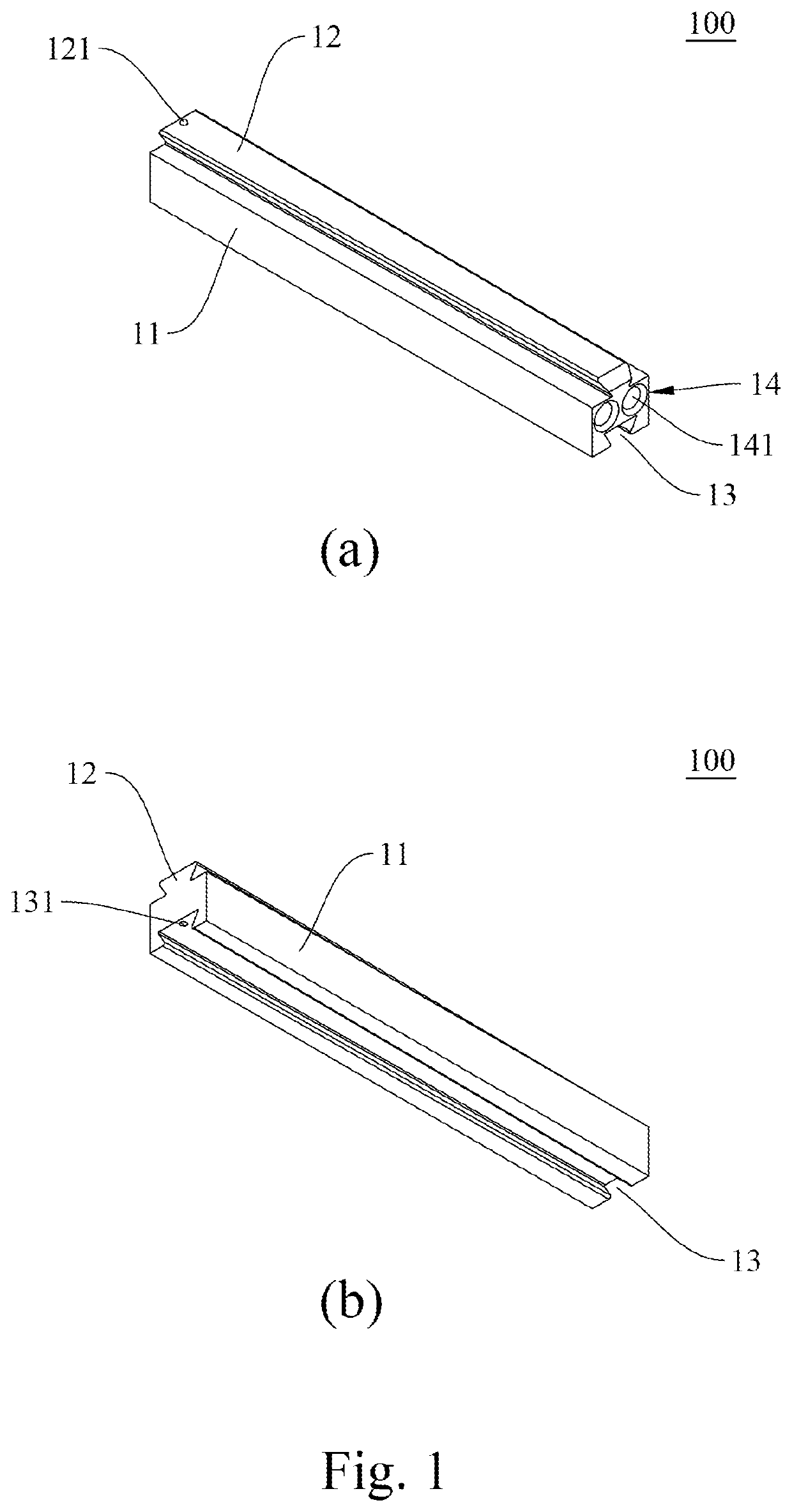
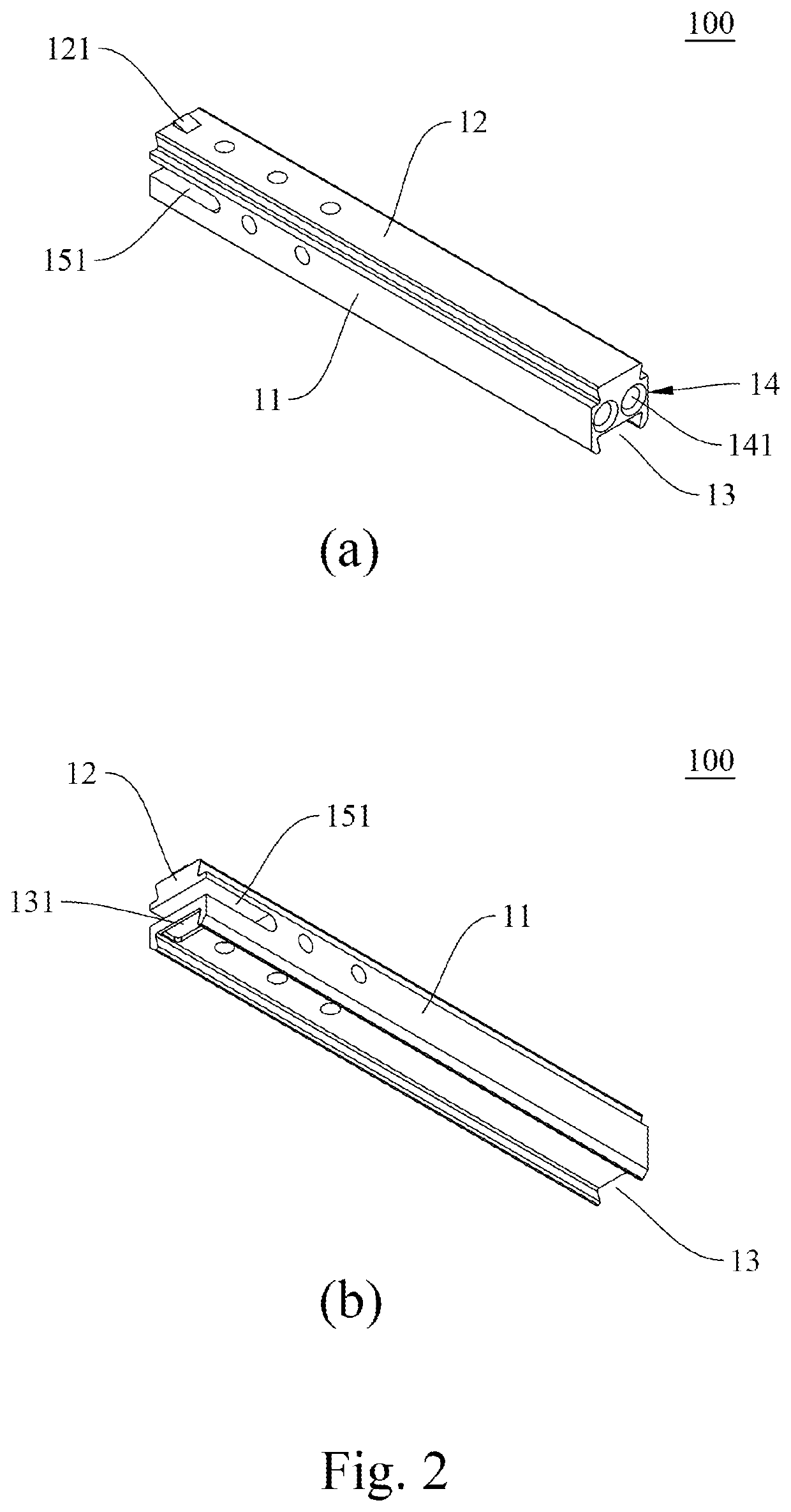
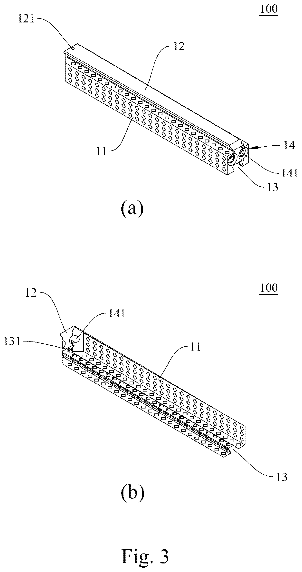
[0050]Please refer to FIG. 1 to FIG. 4 for perspective views of four supporting members 100 according respectively to embodiments 1 to 4 of the present invention.

[0051]The supporting members 100 according to embodiments 1 to 4 are configured to be implanted into or between a subject's bones and each include a main body 11, a first connecting portion 12, a second connecting portion 13, and a guiding structure 14. The main body 11 has an upper side and a lower side, which is the opposite side of the upper side. In embodiment 3, referring to FIG. 3, the main body 11 is preferably one or a plurality of reticulated structures. This embodiment is advantageous in that the at least one reticulated structure can be filled with a bone-filling material (e.g., bone cement), provides space for the proliferation of osteoblasts, allows passage of nutrients, produces a supporting effect similar to that of trabeculae, and facilitates fusion between the main body...

embodiment 5

[Embodiment 5]—Supporting Member Assembly

[0057]Please refer to FIG. 5 and FIG. 6 respectively for a sectional view and a perspective view of the supporting member assembly 200 according to embodiment 5 of the present invention. The supporting members in the supporting member assembly 200 are sequentially identified in a bottom-up order as the first supporting member 21, the second supporting member 22, the third supporting member 23, the fourth supporting member 24, and the fifth supporting member 25. As the supporting members are implanted in the same direction, their guiding structures 213 face the same direction.

[0058]The supporting member assembly 200 according to embodiment 5 is configured to be implanted into or between a subject's bones and includes the plural supporting members stated above, with the first connecting portion of each supporting member (except for the uppermost supporting member 25) forming a dovetail joint with the second connecting portion of the adjacent su...

embodiments 6 and 7

[Embodiments 6 and 7]—Template Plug

[0068]Please refer to FIG. 8 and FIG. 9 for perspective views of two template plugs 400 according respectively to embodiments 6 and 7 of the present invention.

[0069]The template plugs 400 according to embodiments 6 and 7 are both configured to guide the supporting member of the present invention into or between a subject's bones. Each template plug 400 includes a connecting pin 41, an extension portion 42, and a grip portion 43, wherein the extension portion 42 has one end connected to the connecting pin 41 and the opposite end connected to the grip portion 43.

[0070]The connecting pin 41 serves to mate with the guiding structure of a supporting member of the present invention and is therefore configured to match the guiding structure in, for example, position, structure, and / or number. As stated above, the guiding structure of a supporting member of the invention may include guiding holes and a buffer groove, both formed in one side of the main bod...


PUM


Abstract

The present invention provides a supporting member and a supporting member assembly including the same to be implanted into or between a subject's bones, and a template plug and a tamper corresponding to the supporting member. The supporting member comprises a main body; a first connecting portion and a second connecting portion formed on the upper and lower sides of the main body respectively and forming a dovetail joint with each other; and a guiding structure formed at a side of the main body and including guiding holes as well as a buffer groove for mating with an external template plug. The supporting members of the invention can be sequentially implanted and connected into a bone or between two connected bones, and improve the defect of the conventional one-size giant implants injuring the surrounding nerves.

Description

BACKGROUND OF THE INVENTION1. Technical Field[0001]The present invention relates to a supporting member and a supporting member assembly to be implanted into or between a subject's bones, and a template plug and a tamper corresponding to the supporting member. More particularly, the invention relates to a supporting member that can be connected with at least one supporting member of the same structure as its own in a bone or between two connected bones, a supporting member assembly composed of such supporting members, and a template plug and a tamper corresponding to such supporting members.2. Description of Related Art[0002]The societies many of us live in are aging or aged, which raises concerns about health issues of the elderly. A senior citizen tends to suffer from osteoporosis and is therefore prone to bone fractures or even vertebral compression fractures. While vertebral compression fractures in most patients can heal within months, the recovery period is anything but easy. ...

Claims


Application Information

Patent Timeline
IPC IPC(8): A61F2/44A61F2/28
CPCA61F2/447A61F2002/30164A61F2/2846A61B17/8852A61F2/4455A61F2/4611A61F2/4614A61F2002/30331A61F2002/30387A61F2002/30599A61F2002/30604A61F2002/30616A61F2002/30772A61F2002/30784A61F2002/3093A61F2002/4435A61F2002/444A61F2002/448A61F2002/4485A61F2002/4625A61F2002/4627A61F2002/4631A61F2002/4681A61F2/30734A61F2/30749A61B17/7074A61F2002/4687A61F2002/30329A61F2002/30471A61F2002/30672
Inventor HSIEH, JUI-YANG
Owner HSIEH JUI YANG
Why Eureka
Try Eureka