Thermal barrier coating

a technology of thermal barrier coating and coating material, which is applied in the direction of superimposed coating process, machines/engines, mechanical equipment, etc., can solve the problems of reducing the coating strain/stress tolerance, reducing the thermal protection provided to the component, and ultimately delamination of the thermal barrier coating material, so as to reduce the manufacturing time and cost of the component, and the process of forming the coating is simple.

Inactive Publication Date: 2021-08-19
ROLLS ROYCE PLC
View PDF0 Cites 0 Cited by
  • Summary
  • Abstract
  • Description
  • Claims
  • Application Information

AI Technical Summary

Benefits of technology

[0015]It has been found that depositing a nucleation layer on an inner columnar ceramic layer, causes branching of a subsequently deposited outer ceramic layer without the need for the markedly different deposition parameters that are typically required to deposit columnar ceramic and branched ceramic materials. This results in a considerably simpler process for forming the coating which, in turn reduces manufacturing time and costs for the component.

Problems solved by technology

Upon cooling within the columnar grain structure, the infiltrated CMAS solidifies and reduces the coating strain / stress tolerance.
This can result in cracking and ultimately delamination of the thermal barrier coating material.
This, in turn leads to the loss of the thermal protection provided to the component.
One problem with this known combination of an inner columnar layer and outer branched layer is that markedly different deposition parameters are required to achieve the branched grain structure than those needed for the deposition of the columnar layer.
This makes the process of forming the dual layer thermal barrier coating difficult to implement within current industrial scale coating equipment.

Method used


Image

  • Thermal barrier coating
  • Thermal barrier coating
  • Thermal barrier coating

Examples


Embodiment Construction

[0072]First, a comparative sample was prepared using a metallic nickel-based substrate which was treated by grit-blasting using #220 brown alumina and subsequently coated with an aluminide bond coat layer.

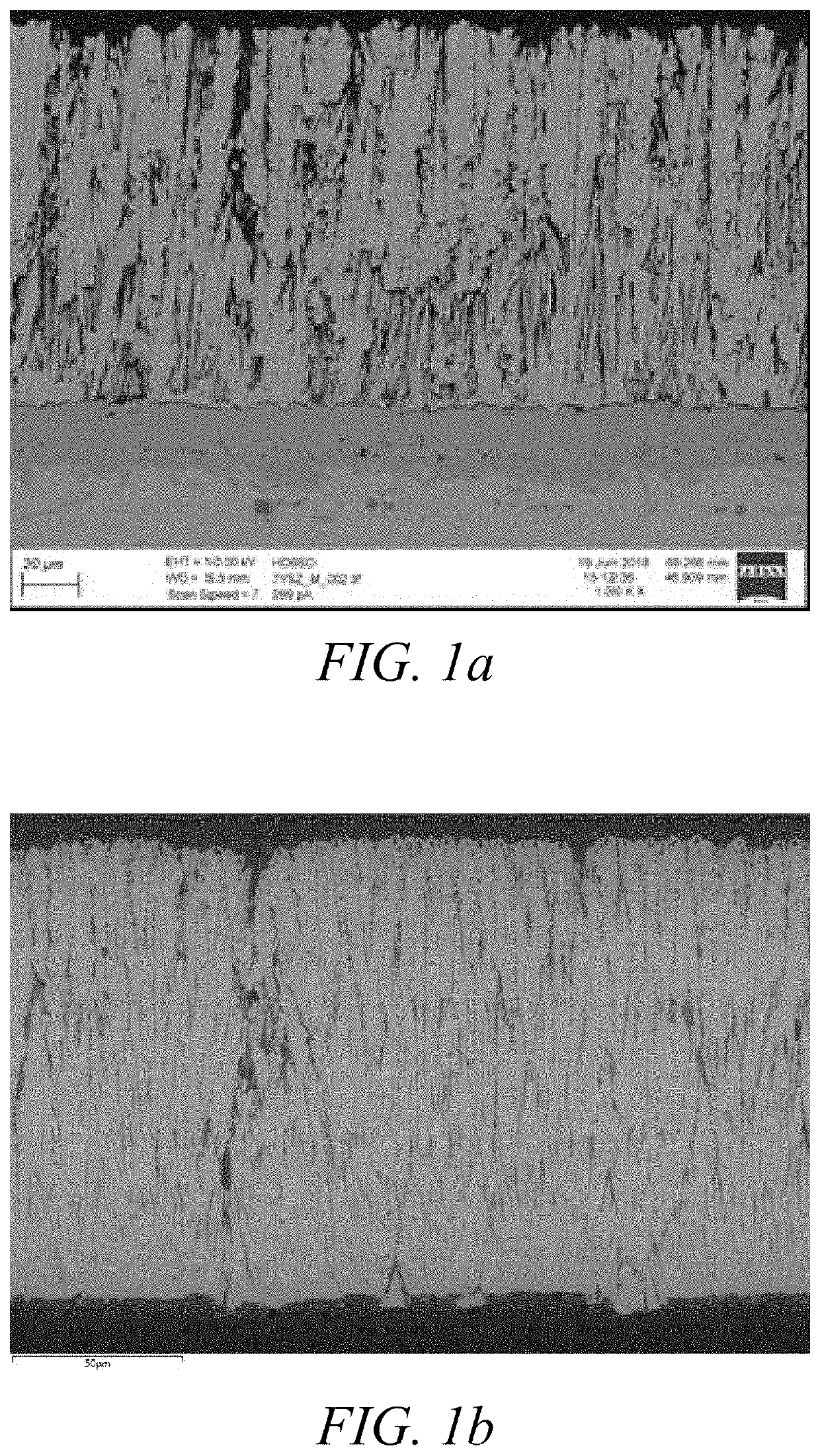
[0073]A ceramic layer having a columnar grain structure, a thickness of 135 microns and comprising 7-9 wt % yttria-stabilised zirconia (7YSZ) was deposited on the substrate using electron beam-physical vapour deposition (EB-PVD) at a temperature of 980° C., a power of 36 kW and a chamber pressure of 6×10⁻³ mbar.

[0074]The resulting columnar ceramic layer is shown in FIG. 1a. The columnar grain structure is clearly visible with the ceramic layer comprising multiple parallel columns extending away perpendicularly to the surface of the substrate, the columns spaced by inter-columnar gaps. These gaps provide for thermal stress / strain tolerances by allowing independent movement of the columns.

[0075]Next, the CMAS resistance of the sample was tested by using an air spray gun to deposit an...


PUM

PropertyMeasurementUnit
thicknessaaaaaaaaaa
thicknessaaaaaaaaaa
thicknessaaaaaaaaaa

Abstract

The present disclosure relates to a thermal barrier coating for coating a substrate. The thermal barrier coating may comprise an inner ceramic layer (e.g. 7YSZ) having a columnar grain structure and a first outer ceramic layer (e.g. 7YSZ) having a branched grain structure. The thermal barrier coating further comprises a nucleation layer (which may comprise alumina or tantala), interposed between the inner ceramic layer and the first outer layer. The layers can be deposited by PVD using substantially contact deposition parameters because the nucleation layer induces branching in the first outer ceramic layer.

Description

CROSS-REFERENCE TO RELATED APPLICATIONS[0001]This specification is based upon and claims the benefit of priority from UK Patent Application Number GB1918278.1 filed on 12 Dec. 2019, the entire contents of which are incorporated herein by reference.FIELD OF THE DISCLOSURE[0002]The present disclosure relates to thermal barrier coatings for protection of components against environmental contaminants. The present disclosure also relates to components (e.g. gas turbine engine components) with such coatings and a method for preparing such coated components.BACKGROUND OF THE DISCLOSURE[0003]Gas turbine engines comprise a number of components (e.g. blades, vanes, nozzles and shrouds in the combustor or turbine engine sections) that are provided with a thermal barrier coating barrier to limit the exposure of the component to the operating temperature of the gas turbine engine.[0004]The thermal barrier coating usually comprises a ceramic material, such as a chemically (metal oxide) stabilized...

Claims


Application Information

Patent Timeline
Patent Type & Authority Applications(United States)
IPC IPC(8): C23C28/00C23C14/08C23C14/04C23C14/54F01D5/28C23C14/24
CPCC23C28/3455C23C14/081C23C14/083C23C14/24C23C14/54F01D5/288C23C14/04C23C4/02C23C4/18C23C14/024C23C14/08C23C28/04C23C28/042C23C28/32C23C28/345C23C28/40C23C28/42C23C4/11C23C4/134
Inventor BREWSTER, JAMES G.CHALK, CHRISTINEAPPLETON, MATTHEW C.
Owner ROLLS ROYCE PLC
Why Eureka
Try Eureka