Substrate process apparatus

a technology of process apparatus and substrate, which is applied in the direction of conveyors, process and machine control, instruments, etc., can solve the problems of increasing the number of actuators, limited mechanical stroke of conventional wafer handlers, and operating in vacuum

Active Publication Date: 2021-08-26
BOOKS AUTOMATION US LLC
View PDF0 Cites 4 Cited by
  • Summary
  • Abstract
  • Description
  • Claims
  • Application Information

AI Technical Summary

Benefits of technology

[0005]In the case of linear tool configurations, “long reach” manipulators with long arm link lengths and articulated end effectors are generally employed to transfer wafers between the load locks and process modules of the linear tool. These long reach manipulators generally have mechanical designs with low natural frequencies, an increased numbers of actuators, undesirable arm link deflection, mechanical positioning hysteresis, high sensitivity to thermal expansion, expensive bearings, limited ability to level the end effector to wafer holding stations, and limited motion throughput. In addition, linear tool configuration may be scalable in the sense of allowing an end-user to extend a length of the linear tool with minimum impact to the existing automation. Another desirable feature of linear tools is the ability to service the linear tool (such as to perform scheduled maintenance on a wafer handler) with minimum disruption to tool operation.

Problems solved by technology

The wafer handlers are also generally mounted to a vacuum cluster tool and their mechanical stroke is limited by the design of their associated arm link lengths.
As a result, conventional wafer handlers, operating in a vacuum, are not suitable for “long” vacuum cluster tools such as what are known in the industry as “linear tool configurations”.
These long reach manipulators generally have mechanical designs with low natural frequencies, an increased numbers of actuators, undesirable arm link deflection, mechanical positioning hysteresis, high sensitivity to thermal expansion, expensive bearings, limited ability to level the end effector to wafer holding stations, and limited motion throughput.

Method used


Image

  • Substrate process apparatus
  • Substrate process apparatus
  • Substrate process apparatus

Examples


Embodiment Construction

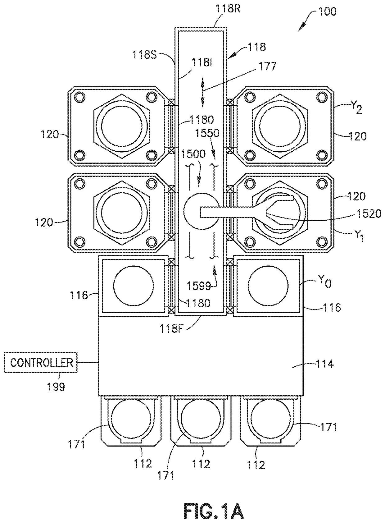
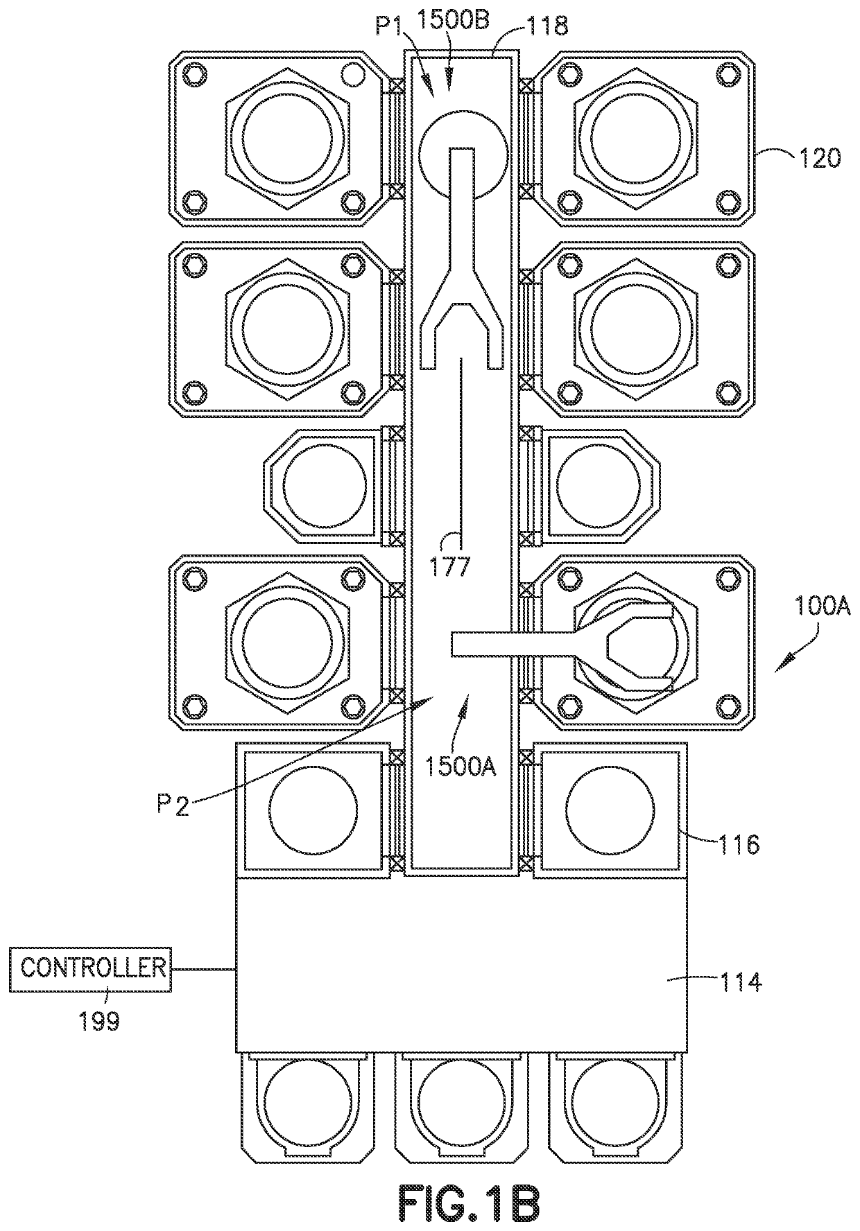
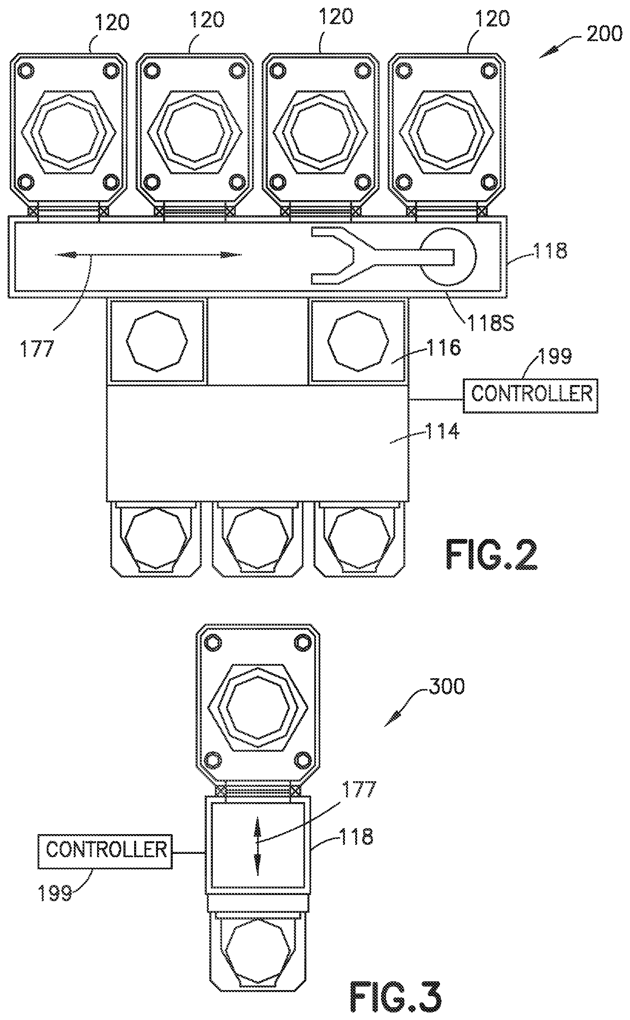
[0070]FIGS. 1-14 illustrate exemplary substrate processing apparatus 100, 100A, 200, 300, 400, 500, 800, 900, 1200, 1300 in accordance with aspects of the disclosed embodiment. Although the aspects of the disclosed embodiment will be described with reference to the drawings, it should be understood that the aspects of the disclosed embodiment can be embodied in many forms. In addition, any suitable size, shape or type of elements or materials could be used.

[0071]Based on the problems and limitations of conventional substrate processing apparatus noted above, it is desirable to have a new and innovative substrate handler and associated controls framework that are configured to operate in vacuum environment substantially without bearing and lubricants, perform substrate transfers across scalable distances without impacting the substrate handler design, transport substrates at higher accelerations than the conventional solutions noted above (i.e., substantially without requiring new en...


PUM


Abstract

A linear electrical machine comprising a frame with a level reference plane and an array of electromagnets, connected to the frame to form a drive plane at a predetermined height relative to the reference plane. The array of electromagnets being arranged so that a series of electromagnets of the array of electromagnets define at least one drive line within the drive plane, and each of the electromagnets being coupled to an alternating current power source energizing each electromagnet. At least one reaction platen of paramagnetic, diamagnetic, or non-magnetic conductive material disposed to cooperate with the electromagnets of the array of electromagnets so that excitation of the electromagnets with alternating current generates levitation and propulsion forces against the reaction platen that controllably levitate and propel the reaction platen along at least one drive line, in a controlled attitude relative to the drive plane.

Description

CROSS REFERENCE TO RELATED APPLICATIONS[0001]This application is a non-provisional and claims the benefit of U.S. Provisional Patent Application No. 62 / 979,195, filed Feb. 20, 2020, the disclosure of which is incorporated herein by reference in its entirety.BACKGROUND1. Field[0002]The exemplary embodiments generally relate to substrate processing equipment, and more particularly, to substrate transports of the substrate processing equipment.2. Brief Description of Related Developments[0003]Semiconductor automation generally comprises a series of building blocks that are required to support the implementation of processes to ultimately achieve predetermined levels of quality and reproducibility in semiconductor chip manufacturing. One component of semiconductor automation is the wafer (also referred to as a substrate) handler that transports the wafer or substrate between load locks and process modules and / or between process modules (e.g., in the case of sequential process tool archi...

Claims


Application Information

Patent Timeline
Patent Type & Authority Applications(United States)
IPC IPC(8): H01L21/677H02N15/00H02K41/025B65G54/02B65G35/06G05D3/12
CPCH01L21/67709H02N15/00H02K41/025H02K2201/18B65G35/06G05D3/125B65G54/02H01L21/67742H01L21/67161H01L21/67727H01L21/67196H01L21/67715H01L21/67253H01L21/67248H01L21/67259
Inventor MOURA, JAIRO T.BOTEV, ROUMEN
Owner BOOKS AUTOMATION US LLC
Why Eureka
Try Eureka