Rectifier circuit, power supply device, and rectifier circuit drive method
a rectifier circuit and power supply device technology, applied in the direction of electric variable regulation, process and machine control, instruments, etc., can solve problems such as loss (more specifically, switching loss), and achieve the effect of effectively reducing a transient curren
- Summary
- Abstract
- Description
- Claims
- Application Information
AI Technical Summary
Benefits of technology
Problems solved by technology
Method used
Image
Examples
first embodiment
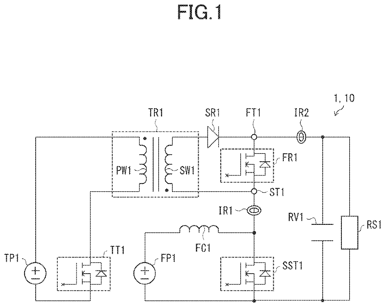
[0023]Described below is a rectifier circuit 1 of a first embodiment. For convenience of description, members of a second embodiment and any subsequent embodiments that have the same function as members described in the first embodiment will be indicated by the same reference numerals, and the description thereof shall be omitted.
[0024]Purpose of Rectifier Circuit 1
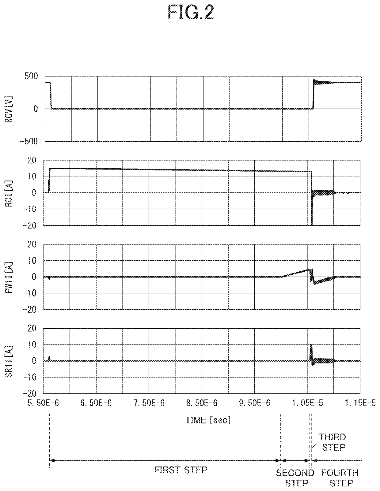
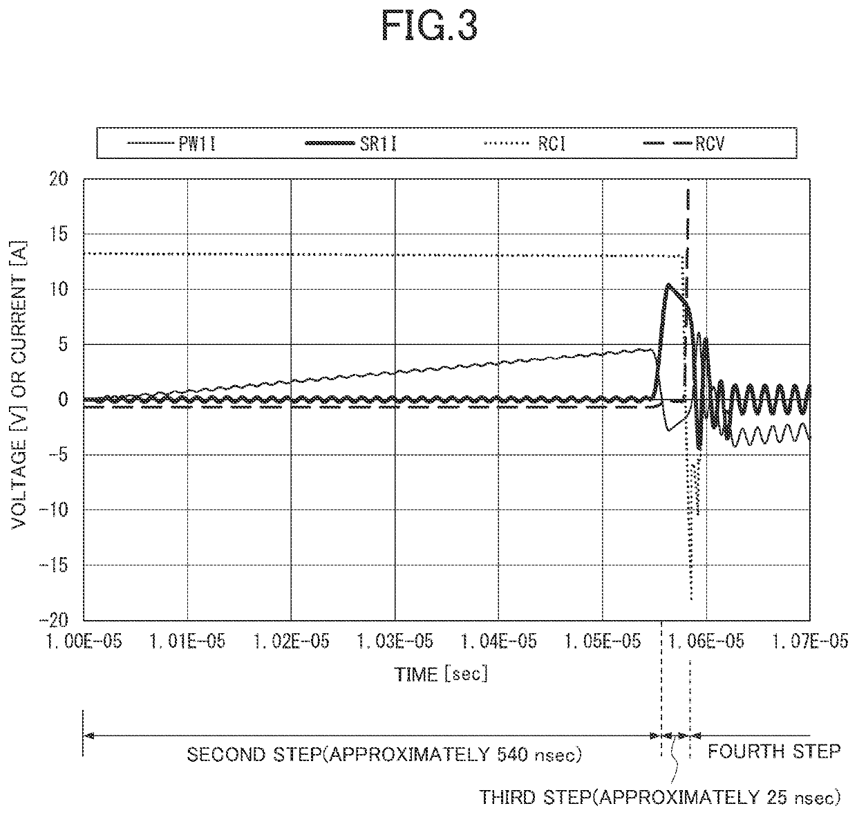
[0025]As described above, a rectifier having a PN junction conducts a reverse recovery current (a transient current). Recent years have seen active developments of rectifiers (compound semiconductor devices) with no PN junction. Examples of such rectifiers include SiC-Schottky barrier diodes (SBDs) or GaN-high electron mobility transistors (HEMTs). The rectifiers do not have any PN junction to store electric charges. Hence, such a rectifier does not generate a reverse recovery current.
[0026]The rectifier, however, has parasitic capacitance. Hence, when a voltage (corresponding to a reverse voltage of the PN junction) is a...
second embodiment
[0176]FIG. 10 is a circuit diagram of a power supply circuit 20 according to a second embodiment. A rectifier circuit according to the second embodiment is referred to as a rectifier circuit 2. In the rectifier circuit 2, the power supply TP1 of the rectifier circuit 1 is replaced with another power supply FP1. That is, in the power supply circuit 20, an input power supply (the power supply FP1) for a step-up chopper also serves as a power supply for the rectifier circuit 2. Such a feature makes it possible to reduce the total number of the power supplies in the power supply circuit 20, contributing to reduction of costs.
[0177]Moreover, in the rectifier circuit 2, the switch element TT1 of the rectifier circuit 1 is replaced with switch elements TT2. TT3, and TT4. A transformer of the rectifier circuit 2 is referred to as a transformer TR2. In the transformer TR2, a primary winding and a secondary winding are respectively referred to as a primary winding PW2 and a secondary winding ...
third embodiment
[0192]FIG. 11 is a circuit diagram of a power supply circuit 30 according to a third embodiment. A rectifier circuit of the third embodiment is referred to as a rectifier circuit 3. In the rectifier circuit 3, the power supply TP1 of the rectifier circuit 1 is replaced with the capacitor RV1. That is, in the power supply circuit 30, the smoothing capacitor (the capacitor RV1) of the step-up chopper serves as the power supply of the rectifier circuit 3. Such a feature makes it possible to reduce the total number of the power supplies in the power supply circuit 30, contributing to reduction of costs.
[0193]Moreover, in the rectifier circuit 3, the switch element TT1 of the rectifier circuit 1 is replaced with switch elements TT5, TT6, and TT7. A transformer of the rectifier circuit 3 is referred to as a transformer TR3. In the transformer TR3, a primary winding and a secondary winding are respectively referred to as a primary winding PW3 and a secondary winding SW3. The rectifier circ...
PUM
 Abstract
Description
Claims
Application Information
 - R&D
- Intellectual Property
- Life Sciences
- Materials
- Tech Scout
- Unparalleled Data Quality
- Higher Quality Content
- 60% Fewer Hallucinations
Browse by: Latest US Patents, China's latest patents, Technical Efficacy Thesaurus, Application Domain, Technology Topic, Popular Technical Reports.
© 2025 PatSnap. All rights reserved.Legal|Privacy policy|Modern Slavery Act Transparency Statement|Sitemap|About US| Contact US: help@patsnap.com


