Semiconductor device having improved gate leakage current

a technology of mikro-conductor and gate leakage current, which is applied in the direction of mikro-conductor devices, basic electric elements, electrical appliances, etc., can solve the problems of inhibiting the operating voltage of a component, limiting the voltage tolerance performance of gan devices, and affecting the operation of components. the effect of gate leakage curren

Pending Publication Date: 2021-12-23
INNOSCIENCE (ZHUHAI) TECH CO LTD
View PDF1 Cites 2 Cited by
  • Summary
  • Abstract
  • Description
  • Claims
  • Application Information

AI Technical Summary

Benefits of technology

[0006]With the development of wireless communication markets, such as military radar systems, personal mobile phones, and base stations, in recent years, millimeter wave transistors are becoming increasingly important. High electron mobility transistors, such as AlGaN / GaN high electron mobility transistors, made of Group III nitride materials, are always a hot research topic. Gallium nitride has a wide bandgap, a high breakdown voltage, a high peak electron velocity, a high electron saturation velocity, strong bonding force and excellent thermal stability, so the gallium nitride has the opportunity to become a main material of the next generation of power devices.
[0007]Compared with the first generation semiconductor materials of silicon (Si) and the second generation semiconductor materials of gallium arsenide (GaAs), the third generation semiconductors have the unique performance of large bandgap width, high breakdown electric field, high thermal conductivity, high electron saturation drift speed, small dielectric constant and the like, so that they show great potentials in aspects of photoelectric devices, power electronics, radio frequency (RF) and microwave power amplifiers, lasers, detection devices and the like.
[0009]In the AlGaN / GaN material system, due to extremely strong spontaneous polarization and piezoelectric polarization effects, unintentional doping may also form a high-concentration electron channel. Under this condition, since there is no scattering caused by donor impurities in the channel, electrons may move at a high speed, and very high electron mobility is obtained. A final result is that an electron thin layer with high concentration and high mobility is generated in the heterostructure, thereby resulting in very low channel resistivity. This is generally known as two-dimensional electron gas (2DEG). In the field effect transistors (FETs), the operation of the transistor is accomplished by changing the conductivity of this layer by applying a bias voltage to a gate electrode, and this is an advantage not found in the second generation semiconductor materials (such as gallium arsenide).
[0013]The energy gap of GaN is as high as 3.39 eV, and the breakdown voltage also reaches 3.3 MV / cm. From the two points, the possibility of GaN for preventing the electronic pulse attack can be improved, and GaN can also work normally in a high-temperature environment.
[0016]In various embodiments, the present invention provides precisely designed HEMT gate structures. The gate structures effectively improve the gate leakage current characteristics of the HEMT devices, thereby achieving the requirement of reducing the gate leakage current, the requirement of independently modulating the magnitude of the leakage current of each die or switching elements, or the requirement of independently modulating the magnitudes of Jgs and Jgd.
[0020]Unexpectedly, the present invention may effectively improve the gate leakage current phenomenon of the HEMT device through the precisely designed gate structure, and the magnitudes of the gate-to-source leakage current (Jgs) and the gate-to-drain leakage current (Jgd) may even be separately adjusted as required.

Problems solved by technology

However, many different physical effects limit the voltage tolerance performance of GaN devices.
In many cases, the maximum allowable operating voltage is limited by an excessive gate leakage current.
The excessive gate leakage current may inhibit the operating voltage of a component.

Method used


Image

  • Semiconductor device having improved gate leakage current
  • Semiconductor device having improved gate leakage current
  • Semiconductor device having improved gate leakage current

Examples


Embodiment Construction

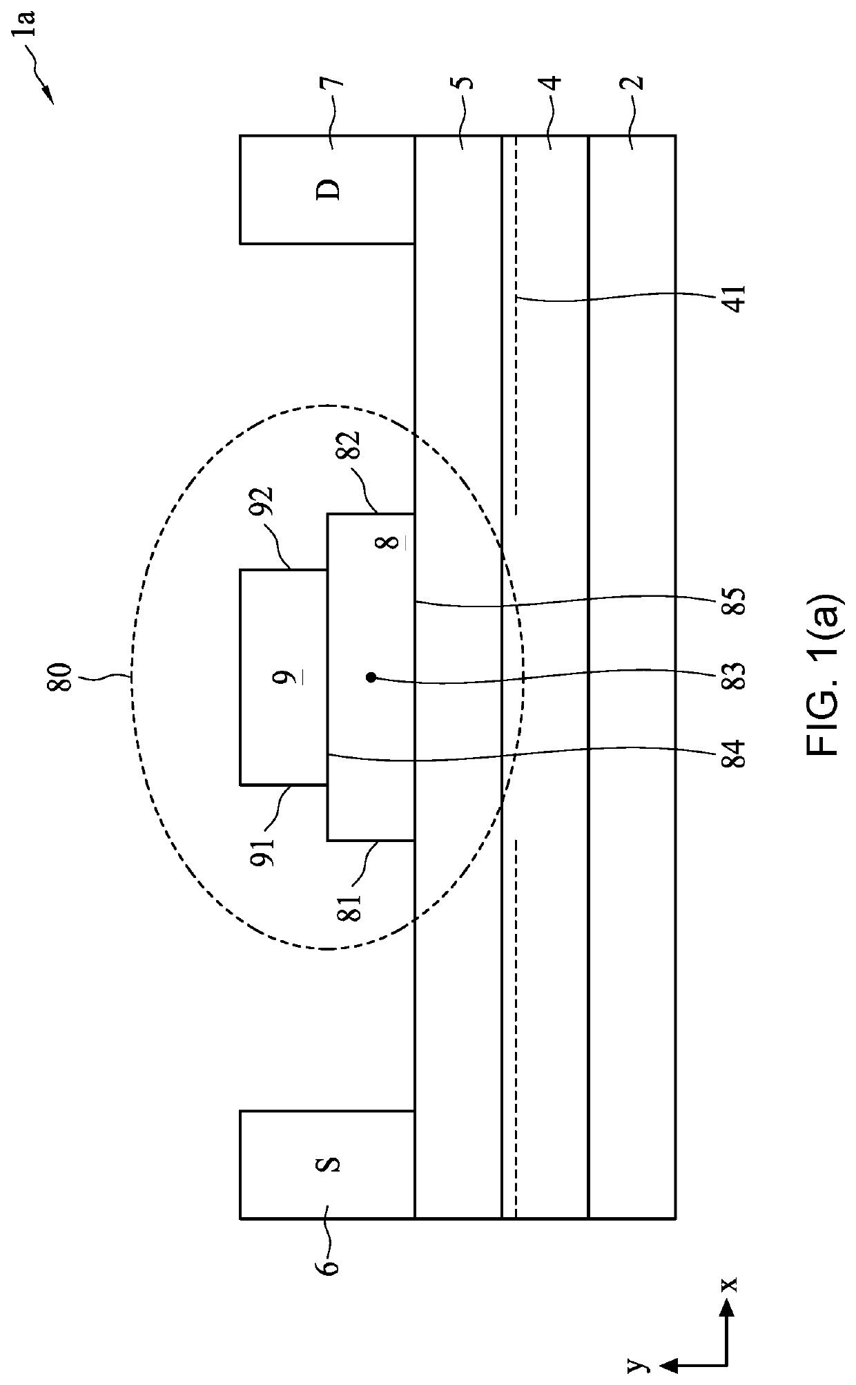
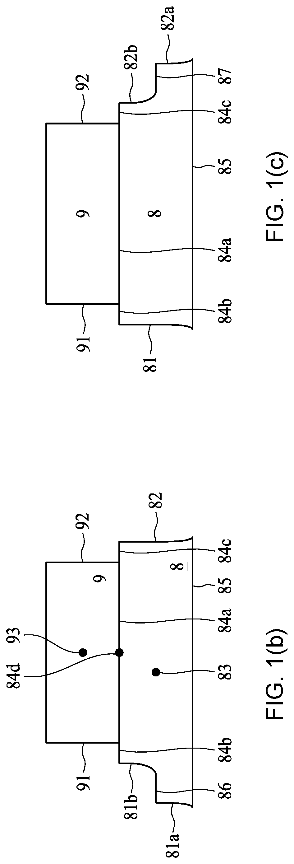
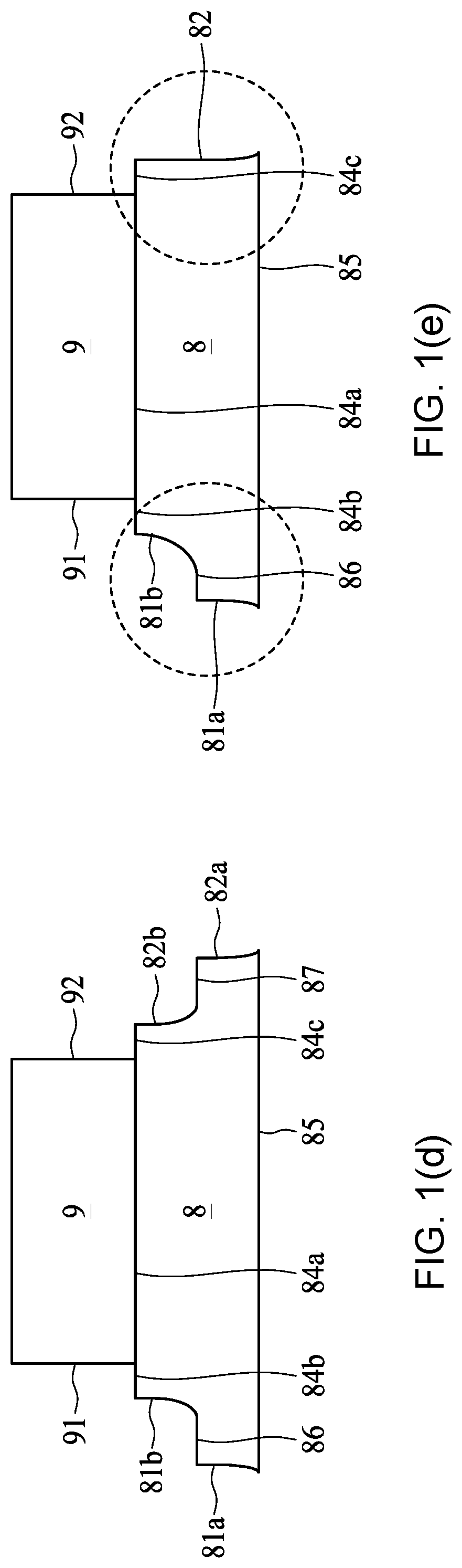
[0039]To make the figures clear and concise, unless otherwise specified, the same reference numerals in different figures indicate the same components. In addition, to simplify the description, descriptions and details of well-known steps and components may be omitted. Although devices may be described herein as some n-channel or p-channel devices or some n-type or p-type doping devices, it is found through effortful research that, the present invention may also be applied to complementary devices. The word “substantially” or “basically” used herein means that a value of a component has a parameter that is expected to be close to a stated value or position. However, as is well known in the art, there are always small differences that prevent a value or position from being exactly the stated value or position. It is acknowledged in the art that a deviation of up to at least ten percent (10%) (and even to twenty percent (20%) for some components including semiconductor doping concentr...


PUM

PropertyMeasurementUnit
angleaaaaaaaaaa
energy gapaaaaaaaaaa
roughnessaaaaaaaaaa

Abstract

The present invention relates to a semiconductor device having an improved gate leakage current. The semiconductor device includes: a substrate; a first nitride semiconductor layer, positioned above the substrate; a second nitride semiconductor layer, positioned above the first nitride semiconductor layer and having an energy band gap greater than that of the first nitride semiconductor layer; a source contact and a drain contact, positioned above the second nitride semiconductor layer; a doped third nitride semiconductor layer, positioned above the second nitride semiconductor layer and between the drain contact and the source contact; and a gate electrode, positioned above the doped third nitride semiconductor layer, where the doped third nitride semiconductor layer has at least one protrusion extending along a direction substantially parallel to an interface between the first nitride semiconductor layer and the second nitride semiconductor layer, thereby improving the gate leakage current phenomenon.

Description

BACKGROUND OF THE INVENTION1. Field of the Invention[0001]The present invention relates to a semiconductor device and a manufacturing method thereof, and particularly to a semiconductor device with a group III-V layer, two-dimensional electron gas, conductor structures, and metal layers.2. Description of the Related Art[0002]GaN switching power transistors can realize a new generation of small-size high-efficiency power converters. Through high switching speeds of the devices, the switching frequency can be improved to realize maintenance or even increase of the total efficiency while reducing the volume and the weight. Due to the physical properties of GaN / AlGaN materials, a high breakdown voltage and a high current level can be achieved at the same time over the small semiconductor area, and the material properties are converted into the high switching frequency at a high power level. However, many different physical effects limit the voltage tolerance performance of GaN devices. ...

Claims


Application Information

Patent Timeline
Patent Type & Authority Applications(United States)
IPC IPC(8): H01L29/778H01L29/20
CPCH01L29/7787H01L29/2003H01L29/42376H01L29/475H01L29/0684H01L29/66462H01L29/7786H01L29/1066H01L29/404H01L29/402H01L27/0605H01L21/8252H01L27/085
Inventor LIAO, HANGZHAO, QIYUELI, CHANG ANWANG, CHAOZHOU, CHUNHUAWONG, KING YUEN
Owner INNOSCIENCE (ZHUHAI) TECH CO LTD
Why Eureka
Try Eureka