
System and method for intermittent electrical modulation

a technology of electrical modulation and system, applied in the field of system and method of intermittent electrical modulation, can solve the problems of limited patient's freedom of movement, significant risk of infection of the body, and additional costs of pulse generators and their batteries

Pending Publication Date: 2022-01-06
ACADEMISCH ZIEKENHUIS BIJ DE UNIV VAN AMSTERDAM ACADEMISCH MEDISCH CENT
View PDF0 Cites 0 Cited by
  • Summary
  • Abstract
  • Description
  • Claims
  • Application Information

AI Technical Summary

Benefits of technology

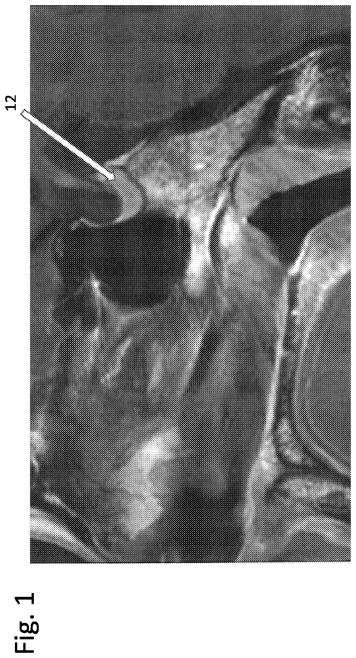
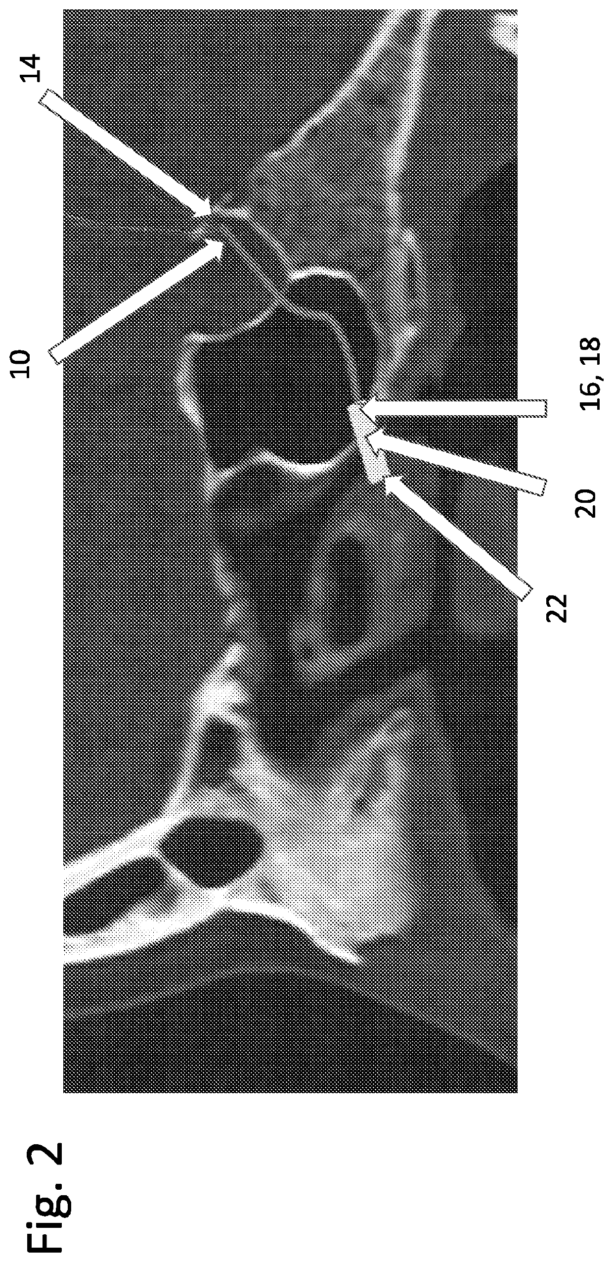
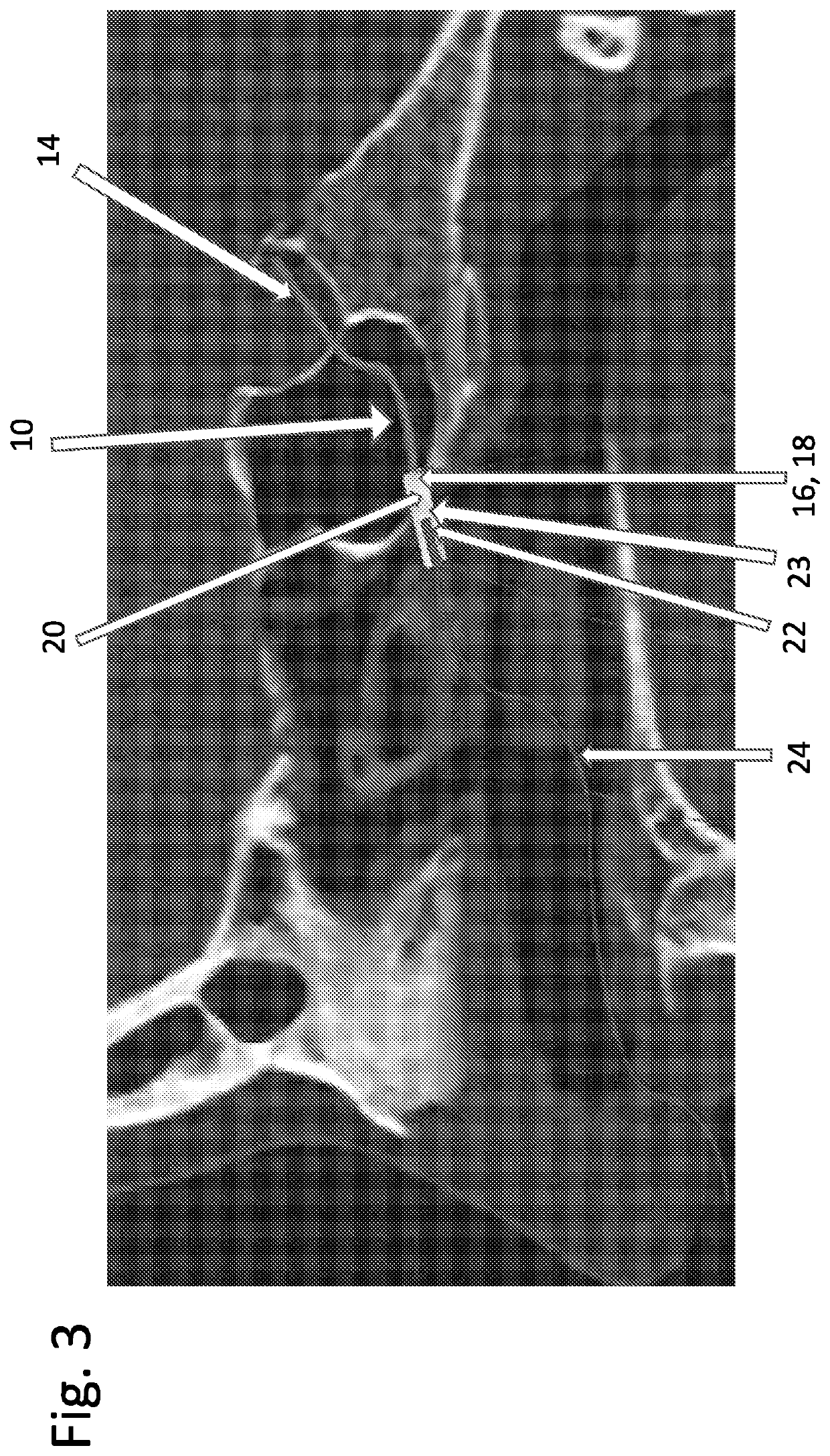
This patent describes a system and method for intermittent electrical stimulation therapy using a flexible electrode array that can be implanted in an organ, such as the pituitary gland, of a mammalian patient. The electrodes can move within a catheter and make conformal contact with the organ tissue. The system includes a connection plug that can be attached to a bone adjacent the organ, and a wire that connects to a source of electrical stimulation. The method involves introducing the electrode array into the organ through an endovascular route and using the conformable device to monitor or actuate the organ's electrical activity. The technical effects include improved precision and efficiency in stimulating targeted areas of the organ and reduced risk of damage to surrounding tissues.

Problems solved by technology

Such an open connection has, however, carried a significant risk of infection of the body and limited the patient's freedom of movement.
Implantation of pulse generators with their batteries has had disadvantages when only used for intermitted treatments, such as requiring additional surgery with resulting discomfort and risks, involving additional costs of the pulse generators and their batteries, involving limited battery lives necessitating replacement surgery, involving more difficulties to adjust stimulation settings for each specific stimulation session, and requiring more difficult to update software.
However, there has been a problem in providing intermittent electrical power to an electrode, when implanted in an organ of a patient.
Previous solutions have not been entirely satisfactory.
However, maintaining an electrical connection through the surgical route used to insert the electrode may entail unnecessary line connections.

Method used


Image

  • System and method for intermittent electrical modulation
  • System and method for intermittent electrical modulation
  • System and method for intermittent electrical modulation

Examples


Embodiment Construction

[0024]In general, the terms and phrases used herein have their art-recognized meaning, which can be found by reference to standard texts, journal references and contexts known to those skilled in the art. The following definitions are provided to clarify their specific use in the context of the invention.

[0025]Herein, the term “electrically interfacing” refers to the ability to monitor and / or generate electrical waveforms on the brain surface in regions underlying the device electrodes.

[0026]Herein, the term “brain tissue” refers to brain in the in vivo, in vitro, or the ex vitro environment. The brain may be from a human or a non-human, such as an animal.

[0027]Herein, the term “conformable” refers to a device, material or substrate which has a bending stiffness sufficiently low to allow the device, material or substrate to adopt a desired contour profile, for example a contour profile allowing for conformal contact with a surface having a pattern of relief or recessed features. In ...


PUM


Abstract

The present invention relates to a system and method, in which a distal end of an electrode is implanted in an organ, such as a pituitary gland, for intermittent electrical stimulation thereof and a proximal end of the electrode is provided with a connection plug, a distal end of which can be attached to a bone adjacent the organ, such an anterior wall of the sphenoid sinus / vomer, and a proximal end of which can be reversibly connected electrically to a wire that is connected electrically to a source of electrical stimulation for the organ.

Description

FIELD OF THE INVENTION[0001]The present invention relates to a system and method for providing intermittent electrical stimulation within a body of a mammal patient, particularly to the pituitary gland, pituitary stalk, basal ganglia and / or hypothalamus of the brain of the mammal.BACKGROUND OF THE INVENTION[0002]It is known to implant an electrode coupled to a source of electrical pulses, in a patient's organ to stimulate the organ. For example, electrical stimulation of a patient's brain can give relief to the symptoms of, for example, Parkinson's disease, depression and compulsive disorders.[0003]Electrical stimulation for neuro-modulation within the body of a mammalian patient typically has involved patterns of continuous stimulation over 24 hours per day. Pulse generators with their power sources have therefore been implanted within the body, to avoid having an open connection between implanted electrodes and external hardware. Such an open connection has, however, carried a sig...

Claims


Application Information

Patent Timeline
IPC IPC(8): A61N1/05A61N1/36A61N1/375
CPCA61N1/0539A61N1/0534A61N1/37518A61N1/36071A61N1/3606A61N1/0546A61N1/36017
Inventor VAN FURTH, WOUTER RBIERMASZ, NIENKE R.ZAMANIPOOR NAJAFABADI, AMIR H.
Owner ACADEMISCH ZIEKENHUIS BIJ DE UNIV VAN AMSTERDAM ACADEMISCH MEDISCH CENT
Learn More