Coated die for use in hot stamping

a hot stamping and die technology, applied in the direction of superimposed coating process, manufacturing tools, shaping tools, etc., can solve the problems of high molding pressure on the bending mold and drawing mold, deformation or a dimension change of the die, and high molding pressure on the drawing mold, etc., to achieve excellent galling resistance and abrasion resistance

Pending Publication Date: 2022-02-03
PROTERIAL LTD
View PDF0 Cites 1 Cited by
  • Summary
  • Abstract
  • Description
  • Claims
  • Application Information

AI Technical Summary

Benefits of technology

[0014]According to the present invention, a coated die which is excellent in both galling resistance and abrasion resistance when used in hot stamping can be provided.

Problems solved by technology

Particularly, bending molds and drawing molds are subjected to a high molding pressure, and due to the sliding of the material to be processed and the die, galling is likely to occur.
However, there is a case that deformation or a dimension change of the die due to the high temperature treatment becomes a problem.
In addition, although these treatments are repeatedly performed, the TRD method and the CVD method form a film by using carbon in the steel material of the die base material, and thus if the treatments are repeatedly performed, the carbon near the surface of the die is reduced, which may lead to a decrease of hardness or a decrease of adhesion to the film.

Method used


Image

  • Coated die for use in hot stamping
  • Coated die for use in hot stamping
  • Coated die for use in hot stamping

Examples


example

Example 1

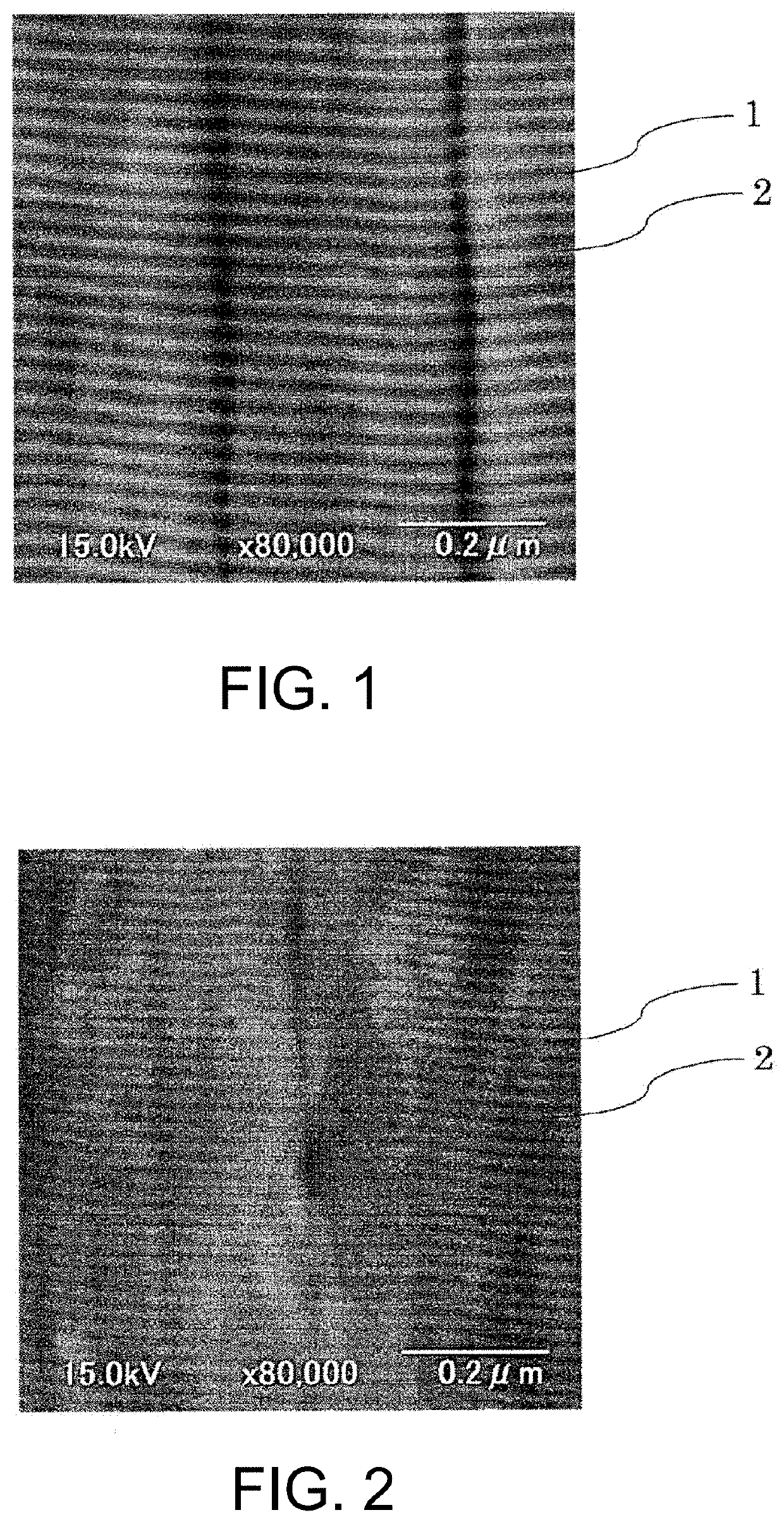
[0037]First, the initial stage of the hot stamping processing was simulated and an adhesion resistance evaluation was performed.

For the substrate, a high-speed steel SKH51 (21 mm×17 mm×2 mm) that has been mirror-polished, degreased and cleaned was prepared, and the prepared substrate was set in an are ion plating device having a structure in which the substrate rotates around a center surrounded by a plurality of targets. An Al60Cr37Si3 target was used as the target for the a1 layer, and a vanadium target was used as the target for the a2 layer. After that, as an initial step, the substrate was heated and degassed at 450° C. in the device, then Ar gas was introduced, and a plasma cleaning treatment (Ar ion etching) of the substrate surface was performed.

Subsequently, nitrogen gas was introduced and the coating was performed on the substrate after the plasma cleaning treatment to produce Sample No. 1 and Sample No. 2. Both Sample No. 1 and Sample No. 2 formed a film (the alt...

example 2

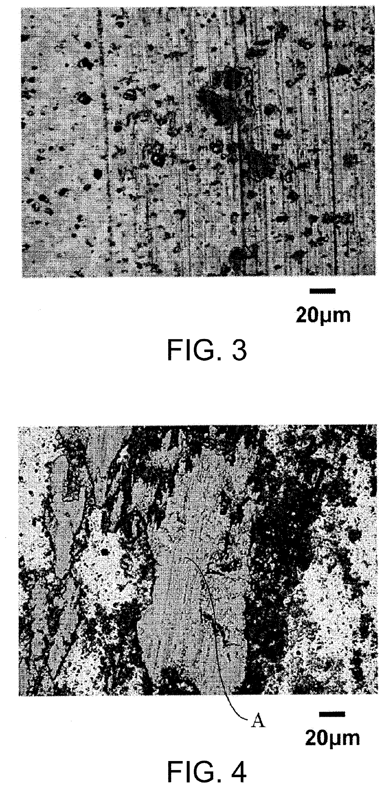
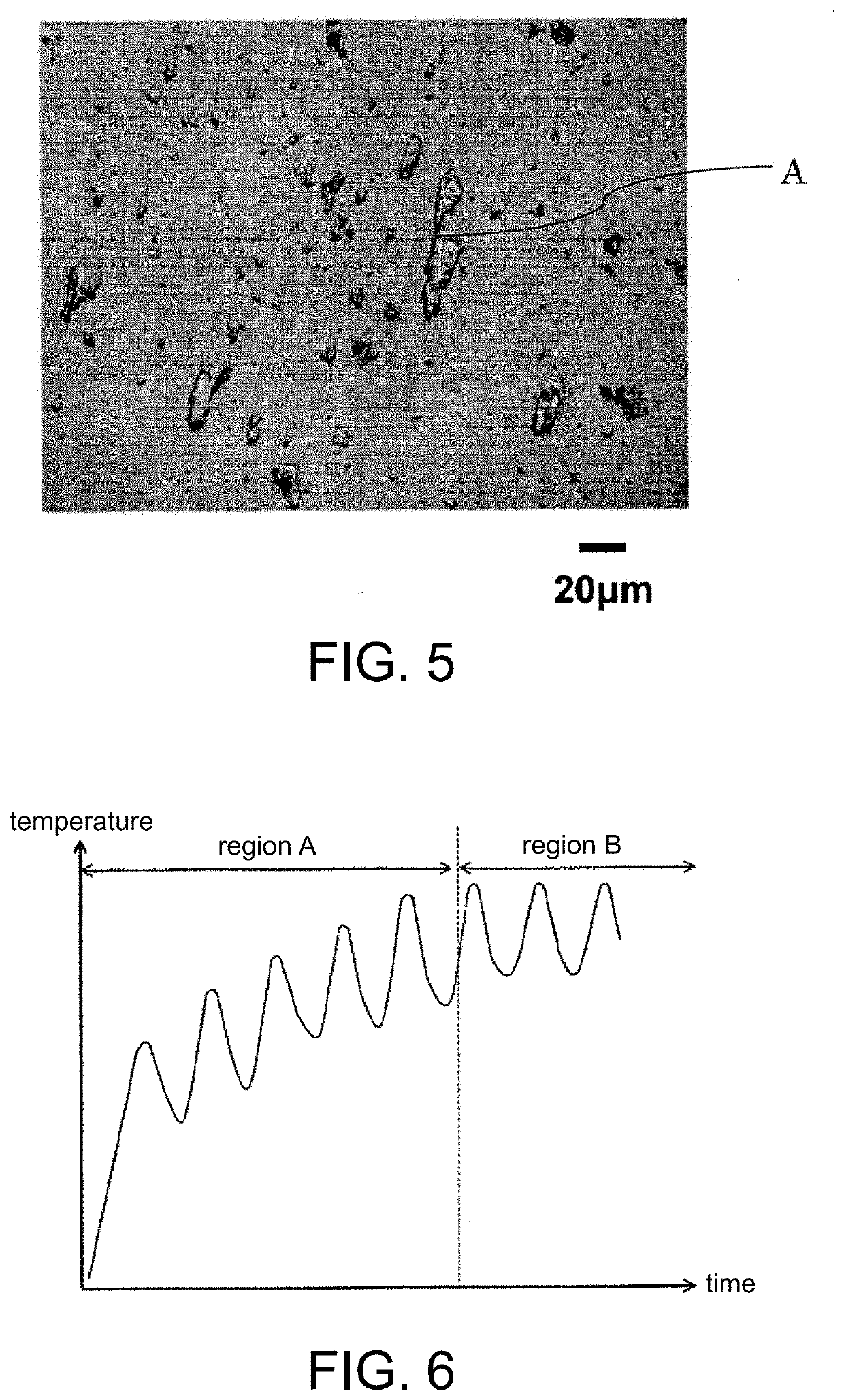
[0039]Subsequently, the intermediate stage of the hot stamping processing was simulated and the abrasion resistance evaluation was performed. Regarding the sample to be evaluated, in addition to Sample No. 1 and Sample No. 2 of Example 1, Sample No. 3 in which the film individual thicknesses of AlCrSiN / VN were adjusted to AlCrSiN: 19 nm, VN: 10 nm (ta2 / ta1=0.52), the total film thickness of the alternating lamination section was set to 19 μm, and other manufacturing methods were the same as Sample No. 1, and Sample No. 4 served as a comparative example which did not contain V and was alternating lamination of AlCrSiN and CrN (the alternating lamination in which AlCrSiN is 23 nm and CrN is 26 nm, and the total thickness was 4.1 μm) were further prepared. A ball-on-disk testing machine (Tribometer manufactured by CSM Instruments) was used for the test. The test environment was set in the atmosphere at 400° C. assuming the intermediate processing of the hot stamping. A pin made of matr...


PUM

PropertyMeasurementUnit
thicknessaaaaaaaaaa
tensile strengthaaaaaaaaaa
total thicknessaaaaaaaaaa

Abstract

A coated die for use in hot stamping has a hard film having an alternating lamination section formed by alternating lamination of a1 layers consisting of nitride having 30% or more of chromium in atomic ratio in a metal part, and a2 layers consisting of nitride having 50% or more of vanadium in atomic ratio in a metal part. When ta1 and ta2 are defined as thicknesses of the a1 layer and the a2 layer respectively, a film thickness ratio Xb is defined as a film thickness ratio ta2/ta1 of a1 layers and a2 layers adjacent to each other in a substrate-side region of the alternating lamination section and a film thickness ratio Xt is defined as a film thickness ratio ta2/ta1 of a1 layers and a2 layers adjacent to each other in an outermost surface side region of the alternating lamination section, it holds that Xt>Xb.

Description

BACKGROUNDTechnical Field[0001]The present invention relates to a coated die coated with a hard film and applied to a die for hot stamping.Related Art[0002]Conventionally, in plastic processing such as forging and press processing, dies are used in which steel typified by tool steel such as cold die steel, hot die steel, and high-speed steel, super hard alloys, or the like are used as a base material. In the plastic processing using a die for press processing or forging, due to the sliding of the work surface of the die and a material to be processed, wear such as abrasion, galling, or the like is likely to occur on the work surface of the die, and the life of the die is desired to be improved. Particularly, bending molds and drawing molds are subjected to a high molding pressure, and due to the sliding of the material to be processed and the die, galling is likely to occur. Galling as used herein refers to a phenomenon in which a chemically active surface is formed on the work surf...

Claims


Application Information

Patent Timeline
Patent Type & Authority Applications(United States)
IPC IPC(8): B21D37/01B21D22/02C23C28/00
CPCB21D37/01B21D22/022C23C28/34C23C28/44C23C28/42C23C28/04C23C28/40C23C8/80C23C8/22C23C8/26C23C14/0641
Inventor SHOUJI, TATSUYA
Owner PROTERIAL LTD
Why Eureka
Try Eureka