
Biofouling protective enclosures

a protective enclosure and biofouling technology, applied in the field of biofouling protective enclosures, can solve the problems of reducing the operation efficiency of the vessel, affecting the effect of the operation of the vessel, and the growth and attachment of various marine organisms to aquatic structures, and achieves the effects of reducing the amount and/or breadth of “free space”, increasing the effective surface area and/or fibrillation of the fabric material, and reducing the average siz

Pending Publication Date: 2022-02-24
BIOFOULING TECH INC
View PDF0 Cites 1 Cited by
  • Summary
  • Abstract
  • Description
  • Claims
  • Application Information

AI Technical Summary

Benefits of technology

The invention is a flexible enclosure that can create a protected area in the water that prevents the growth of sea organisms that cause damage and clogging. The enclosure acts as a barrier to these organisms, while still allowing water to flow through it. The outer surface of the enclosure can be coated with a biocide to further reduce the growth of biofouling. This invention can extend the lifespan of the enclosure and prevent damage to the substrate and other objects attached to it.

Problems solved by technology

The growth and attachment of various marine organisms on structures in aquatic environments, known as biofouling, is a significant problem for numerous industries, including both the recreational and industrial boating and shipping industries, the oil and gas industry, power plants, water treatment plants, water management and control, irrigation industries, manufacturing, scientific research, the military (including the Corps of Engineers), and the fishing industry.
Despite the appearance of simplicity, the process of biofouling is a highly complex web of interactions effected by a myriad of micro-organisms, macro-organisms and the ever-changing characteristics of the aquatic environment.
Large amounts of biofouling on ships can result in corrosion of various surfaces exposed to the aquatic environment, greatly reducing efficacy of the operation of the vessel, and often eventual deterioration of portions of the ship.
Micro and macro organism build-up also causes increases in roughness of the ship's surface such that the ship experiences greater frictional resistance, decreased speed and maneuverability, and increased drag, resulting in increased fuel consumption.
These increased costs are experienced by commercial and recreational boaters alike, as barnacles and other animals attach to propellers, drive system components, inlets and / or hull components submerged in water.
In many cases, even thin biofilms formed on a heat transfer surface will significantly insulate this surface, reducing its heat transfer efficiency and greatly increasing the overall operating costs for the cooling system.
Aside from increasing corrosion and other damage to structures, the weight and distribution of macro-fouling on objects can also dramatically alter the buoyancy or stresses and strains experienced by the object and / or support structures, which can lead to premature failure and / or sinking of the fouled objects.
For example, navigational buoys, containment booms or pier posts containing surfaces with large amounts of biofouling are subjected to increased stress loads resulting from increased weight—and can even founder or sink under excessive amounts of macrofouling.
This increased stress often results in decreasing the useful life of the structures and necessitating continuous cleaning and / or replacement.
Similarly, submerged sensors (including tethered and / or free-floating sensors) will often fail and / or malfunction relatively quickly (often in less than 30 days) due to incursion of and / or colonization by marine organisms.
Biofouling also creates substantial ecological problems by distributing plant and animal species to non-native environments as they “ride along” on the fouled object, and significant legislative and financial resources are allocated to combat the commercial and ecological impacts of biofouling.
However, scraping is labor intensive and can damage fouled surfaces, and environmental issues have been raised over the concerns that scraping results in the increased spread of invasive species, along with negative environmental effects on local fauna.
In addition, many of the enclosure embodiments disclosed by this reference create environments with extremely low dissolved oxygen levels (i.e., 8.3% or less), which tend to be highly anoxic and promote excessive microbial corrosion and degradation of the protected object.
Many of these coatings and / or other materials rely upon biocidal additives and / or metallic additives (i.e., copper) that desirably leach into the surrounding aqueous environment over time and interfere with various aspects of the biofouling organisms.
However, the process of preparing the underwater surface(s) of objects and then applying and / or bonding such paints / coatings directly to such surface(s) is often an expensive and time-consuming process (which can even require removal of an object from the aqueous environment and / or even drydocking of a vessel), and all of these coatings have a limited duration, typically lose effectiveness over time, and often have a deleterious (and unwanted) effect on organisms in the surrounding aqueous environment.
Similar difficulties exist with systems which rely upon ablative and / or surface characteristics such as hydrophobicity, super-hydrophobicity and / or non-adhesive (i.e., non-stick and / or super-ciliated) surfaces.
In addition to the high cost of purchasing and / or operating such systems, such caustic substances (which may be strong oxidizing agents in the case of chlorine) can cause deleterious effects far beyond their intended environment of use (i.e., once released they can damage organisms in the surrounding aquatic environment), and many of these substances can enhance corrosion and / or degradation of the very items or related system components they are meant to protect.
In these cases, however, the liquid contained within the sealed environment (which is also in direct contact with the protected object) typically becomes stagnant and / or anoxic quite quickly, leading to high levels of anaerobic corrosion of various materials, and especially high levels of corrosion in anoxic sulfate-rich environments such as anoxic seawater.

Method used


Image

  • Biofouling protective enclosures
  • Biofouling protective enclosures
  • Biofouling protective enclosures

Examples


Embodiment Construction

[0092]The disclosures of the various embodiments described herein are provided with sufficient specificity to meet statutory requirements, but these descriptions are not necessarily intended to limit the scope of the claims. The claimed subject matter may be embodied in a wide variety of other ways, may include different steps or elements, and may be used in conjunction with other technologies, including past, present and / or future developments. The descriptions provided herein should not be interpreted as implying any particular order or arrangement among or between various steps or elements except when the order of individual steps or arrangement of elements is explicitly described.

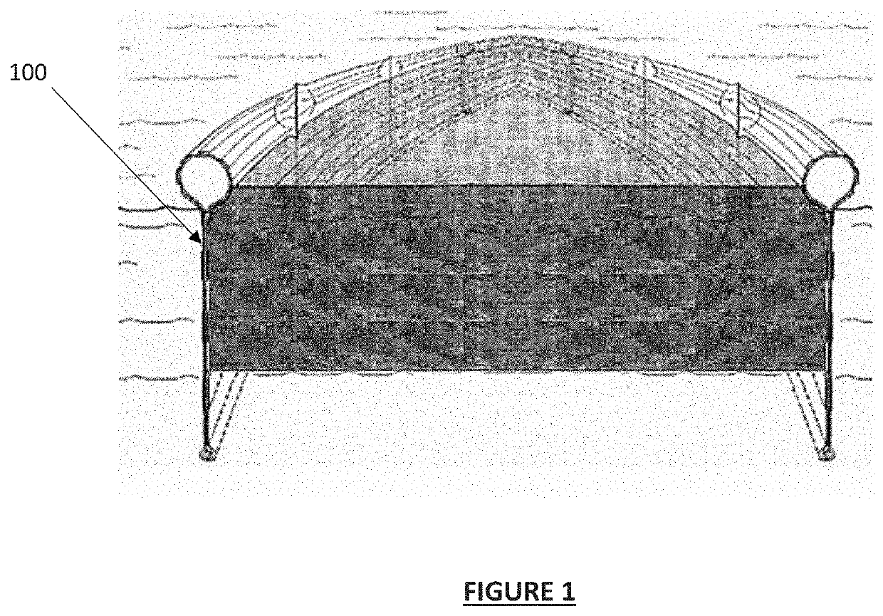
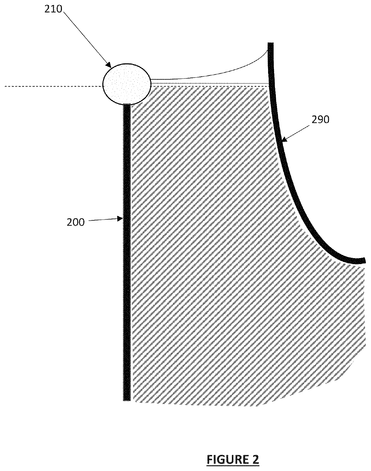
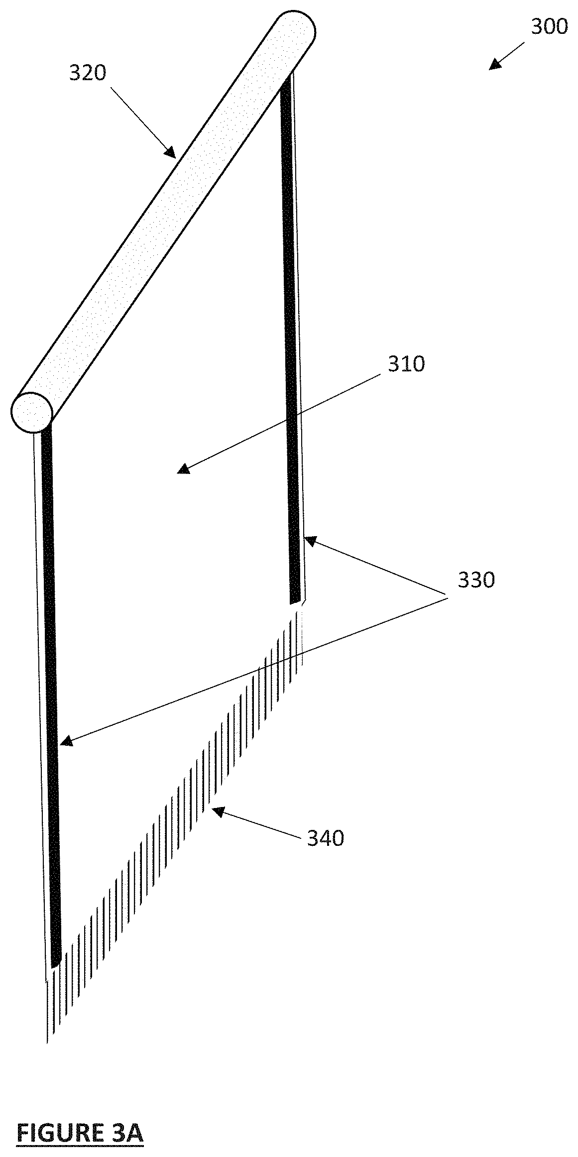
[0093]Disclosed herein are a variety of simple-to-assemble and / or use enclosures and / or other devices which may be placed in proximity to, around, within, on top of and / or below a substrate or other object that is located within (or that is placed within) an aqueous environment or aqueous holding tank t...


PUM


Abstract

Disclosed are devices, methods and / or systems for use in protecting items and / or structures that are exposed to, submerged and / or partially submerged in aquatic environments from contamination and / or fouling due to the incursion and / or colonization by specific types and / or kinds of biologic organisms and / or plants, including the protection from micro- and / or macro-fouling for extended periods of time of exposure to aquatic environments.

Description

CROSS-REFERENCE TO RELATED APPLICATIONS[0001]This application is a continuation of Patent Cooperation Treaty (PCT) Patent Application No. PCT / US2020 / 022782 filed Mar. 13, 2020, titled “BIOFOULING PROTECTION,” which claims priority to and benefit thereof from U.S. Provisional Patent Application No. 62 / 817,873 filed Mar. 13, 2019, titled “BIOFOULING PROTECTIVE ENCLOSURES,” and Patent Cooperation Treaty (PCT) Patent Application No. PCT / US19 / 59546, filed Nov. 1, 2019 and entitled “DURABLE BIOFOULING PROTECTION,” the disclosures of which are each incorporated by reference herein in their entireties.TECHNICAL FIELD[0002]The invention relates to improved devices, systems and methods for use in protecting items and / or structures that are exposed to, submerged in and / or partially submerged in aquatic environments from contamination and / or fouling due to the incursion and / or colonization by specific types and / or kinds of biologic organisms. More specifically, disclosed are improved methods, a...

Claims


Application Information

Patent Timeline
Patent Type & Authority Applications(United States)
IPC IPC(8): B63B59/04B08B17/04
CPCB63B59/04B08B17/04D06M16/00A01N59/00B63B59/045Y02W10/37A01N25/22A01N41/04
Inventor MCMURRAY, BRIANSTEPHENS, ABERALSTON, EMILYTERMINI, MIKESHARPE, CLIFFCALCUTT, LINDSEY
Owner BIOFOULING TECH INC
Learn More