Electrolyte medium for lithium secondary battery and lithium secondary battery

Pending Publication Date: 2022-03-17
HONDA MOTOR CO LTD +1
0 Cites 0 Cited by

AI-Extracted Technical Summary

Problems solved by technology

However, it is known that, in the case of using this lithium metal, lithium precipitates in dendrite form during charging, and thus it is known that a partial short circuit, depletion of electrolytic solution, dropout of precipitated lithium, or the like causes significant cycle degradation.
Further, in high-rate and large batteries, short circuits or the like occur, and safety is an issue.
Therefore, lithium metal secondary batteries are not generally used.
However, since lithium metal is extremely active, it may be altered during the coating process and may be oxidized during alloy production.
Further, if a portion of the coating is missing, there is a possibility that lithium may grow a dendrite therefrom.
Therefore, the proce...

Method used

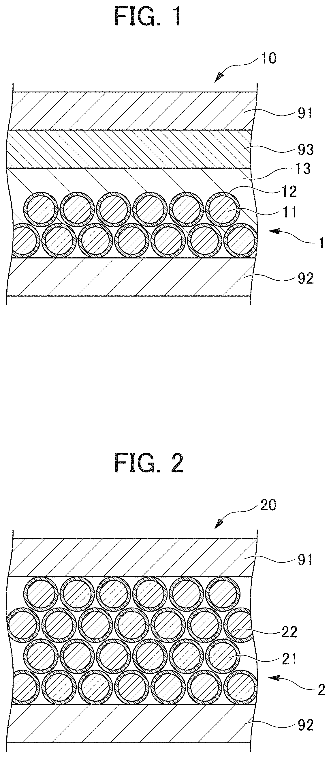
[0052]An electrolyte medium for a lithium secondary battery according to an embodiment of the present invention (hereinafter, also simply referred to as an electrolyte medium) is used in a lithium secondary battery, and includes a low dielectric constant solvent, a lithium salt, and a polyvalent cation salt in a state in which particles of the polyvalent cation salt are dispersed (undissolved state) and can flow without being immobilized. Further, the electrolyte medium according to the present embodiment is characterized in that the content of a high dielectric constant solvent having a higher dielectric constant than that of the low dielectric constant solvent is 20 mass % or less. The electrolyte medium according to the present embodiment having such a configuration allows a lithium secondary battery capable of suppressing short circuits and having high energy density and high output, to be provided.
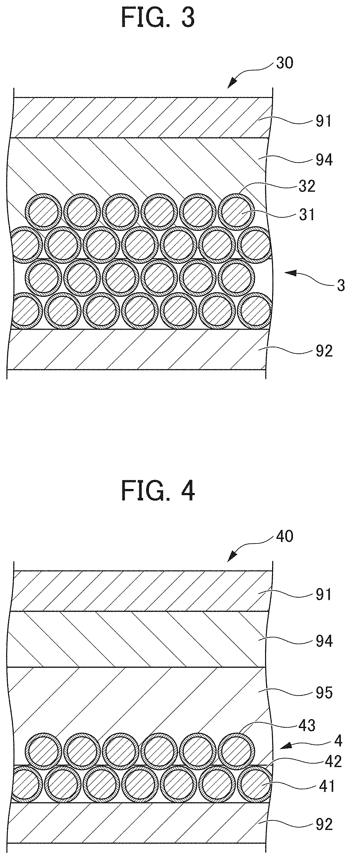
[0053]Further, by including the electrolyte medium according to the embodiment of the present invention, since the particles of the polyvalent cation salt are present on the negative electrode (lithium metal) in a flowing state, a solid electrolyte interphase (SEI) layer having a bulky structure is formed at an interface between the negative electrode and the electrolyte medium, and a short circuit is suppressed. Thus, in a lithium secondary battery provided with the electrolyte medium according to the present embodiment, a lithium metal negative electrode and a nonwoven fabric separator can be used, and a lithium secondary battery with high energy density and high output can be provided.
[0064]In the present embodiment, the polyvalent cation salt is dispersed as particles in the electrolyte medium and the particles can flow without being immobilized. The polyvalent cation salt may be in either a colloidal state or a suspended state in a liquid phase, or a solid phase state. Further, the polyvalent, cation salt may be in the form of colloids or particles in a liquid phase due to the anion of the lithium salt described above, or in a solid phase state due to the thickener described above. Accordingly, since the polyvalent cation salt is present on the negative electrode in a flowing state, an SEI layer having a bulky structure can be formed at an interface between the negative electrode and the electrolyte medium, and thus a short circuit can be suppressed.
[0070]The inclusion state of the polyvalent cation salt in the first to fourth configurations described above means “a state in which particles are dispersed and can flow without being immobilized”. As described above, it is presumed that the particles of the polyvalent cation salt flow without being immobilized and thereby adsorb the electrolytic solution, resulting in a concentrated electrolyte solution in the vicinity of the particles of the polyvalent cation salt, which can suppress a short circuit. Each of the inclusion states of the polyvalent cation salts in the first to fourth configurations can be realized by mixing the low dielectric constant solvent, the high dielectric constant solvent as needed, the lithium salt, and the polyvalent cation salt described above to form the electrolyte medium.
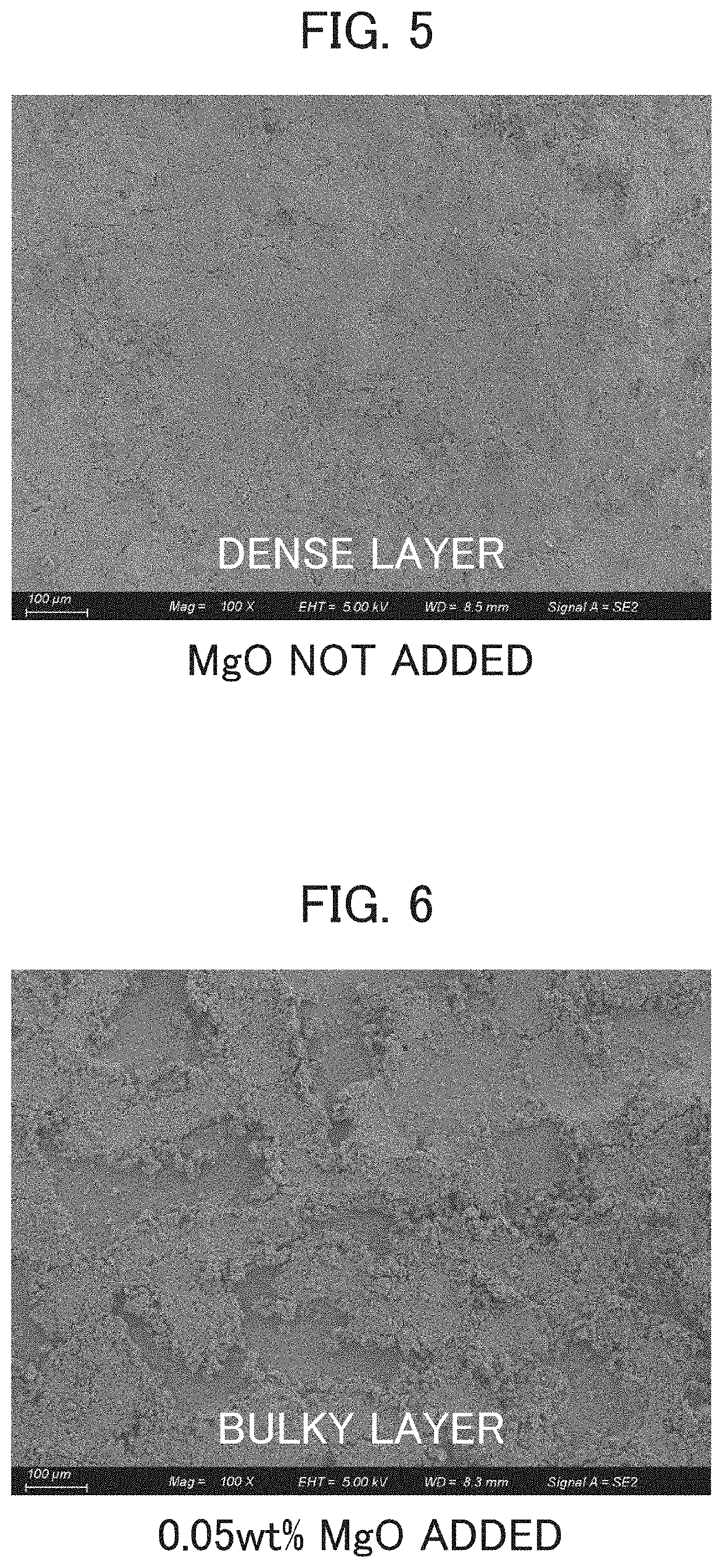
[0073]When an SEI layer having a bulky structure is formed on a negative electrode in this manner, it is considered that the movement of ions is deiocaiized (randomized) and thus a short circuit can be suppressed without preventing a short circuit by a separator. Therefore, the formation of a bulky SEI layer as shown in FIGS. 6 and 7 enables stable cycle characteristics to be obtained. The SEI layer itself is considered to be composed of LiF, COx, or the like, similarly to an SEI layer conventionally known.
[0075]The average particle diameter of the polyvalent cation salt is preferably 100 μm or less. When the average particle diameter of the polyvalent cation salt is 100 μm or less, a short circuit can be suppressed more reliably, and high energy density and high output can be obtained more reliably. When the average particle diameter of the polyvalent cation salt is large, variation in capacity between cycles tends to be large, so that a more preferred average particle diameter of the polyvalent cation salt is 20 μm or less.
[0076]The content of the polyvalent cation salt is preferably 0.1 mass % to 50 mass %. If the content of the polyvalent cation salt is within this range, the negative electrode is covered with a bulky SEI layer, thus obtaining stable charge and discharge characteristics. The high content of the polyvalent cation salt causes the electrolyte medium to become a granular solid and thus can avoid the degradation of rate characteristics. A more preferred content of the polyvalent cation salt is 0.1 mass % to 1.5 mass %.
[0078]The electrolyte medium according to the present embodiment may include a thickener. The addition of a thickener to the electrolyte medium according to the present embodiment described above allows a polyvalent cation salt particle layer to be stably formed.
[0085]In contrast, according to the lithium secondary battery ...

Benefits of technology

[0022]According to the present invention, it is possible to provide the lithium secondary b...

Abstract

To provide a lithium secondary battery capable of suppressing short circuits and having high energy density and high output. An electrolyte medium for a lithium secondary battery includes a low dielectric constant solvent, a lithium salt, and a polyvalent cation salt. The polyvalent cation salt is dispersed as particles in the electrolyte medium and can flow without being immobilized. The electrolyte medium includes 20 mass % or less of a high dielectric constant solvent. A lithium secondary battery including the electrolyte medium for a lithium secondary battery can suppress short circuits and provide high energy density and high output.

Application Domain

Technology Topic

Image

  • Electrolyte medium for lithium secondary battery and lithium secondary battery
  • Electrolyte medium for lithium secondary battery and lithium secondary battery
  • Electrolyte medium for lithium secondary battery and lithium secondary battery

Examples

  • Experimental program(8)

Example

Example 1
[0094]As the lithium secondary battery according to Example 1, a lithium secondary battery having the following configuration was produced. The lithium secondary battery according to Example 1 produced was subjected to charge/discharge tests under the following conditions.
[0095]Negative electrode: Lithium metal
[0096]Positive electrode: Lithium cobaltate
[0097]Separator: Polypropylene nonwoven fabric (porosity 78%)
[0098]Electrolyte medium: 1 M LiPF6/DMC+1.5 mass % MgO (average
[0099]particle diameter: 100 μm)
[0100]25° C., 150 mAhg−1-0.5 C, 100 cycles

Example

Comparative Example 1
[0101]As the lithium secondary battery according to Comparative Example 1, a lithium secondary battery having the following conventional general configuration was produced. The lithium secondary battery according to Comparative Example 1 produced was subjected to charge/discharge tests under the same conditions as in Example 1.
[0102]Negative electrode: Lithium metal
[0103]Positive electrode: Lithium cobaltate
[0104]Separator: Kicroporous sheet-like polypropylene
[0105]Electrolyte medium: 1 M LiPF6/DMC+30 mass % EC
[0106]FIG. 8 is a diagram showing charge/discharge curves of the lithium secondary battery according to Example 1. FIG. 9 is a diagram showing charge/discharge curves of the lithium secondary battery according to Comparative Example 1. In FIGS. 8 and 9, the horizontal axis represents capacity, and the vertical axis represents voltage (the same applies to FIGS. 10 to 28 described later). As shown in FIGS. 8 and 9, the cycle characteristics of the lithium secondary battery according to Comparative Example 1 were significantly degraded, whereas the cycle retention rate of the capacity of the lithium secondary battery according to Example 1 was 97%, which exhibited stable cycle characteristics. From these results, it was confirmed that, stable charge and discharge is possible even when lithium metal is used as a negative electrode and a nonwoven fabric separator is used as a separator, by using the electrolyte medium for a lithium secondary battery of the present invention including a low dielectric constant solvent (DMC), a lithium salt, a polyvalent cation salt (undissolved MgO in an electrolyte medium), and 20 mass % or less of a high dielectric constant solvent. Therefore, it; was confirmed that the present invention can suppress short circuits and provide high energy density and high output.

Example

[0107]As the lithium secondary batteries according to Examples 2 to 4 and Comparative Example 2, lithium secondary batteries each having the following configuration were produced. In other words, the lithium secondary batteries according to Examples 2 to 4 and Comparative Example 2 correspond to the lithium secondary battery of Example 1 described above except that EC, a high dielectric constant solvent, was added to the electrolyte medium. The content of EC in the electrolyte medium was set to 20 mass % in Example 2, 10 mass % in Example. 3, 0 mass % in Example A, and 30 mass % in Comparative Example 2. The lithium, secondary batteries of Examples 2 to 4 and Comparative Example 2 produced were subjected to charge/discharge tests under the following conditions.
[0108]Negative electrode: Lithium metal
[0109]Positive electrode: lithium cobaltate
[0110]Separator: Polypropylene nonwoven fabric (porosity 78%)
[0111]Electrolyte medium: 1.2 M LIPFe/DMC+0.1 mass % MgO (average particle diameter: 100 μm)+0 to 30 mass % EC
25° C., 150 mAhg−1-0.2 C
[0112]FIG. 10 is a diagram showing charge/discharge curves of the lithium secondary battery according to Example 2. FIG. 11 is a diagram showing charge/discharge curves of the lithium secondary battery according to Example 3. FIG. 12 is a diagram showing charge/discharge curves of the lithium secondary battery according to Example 4. FIG. 13 is a diagram showing charge/discharge curves of the lithium secondary battery according to Comparative Example 2. FIGS. 10 to 13 all show initial charge/discharge curves. As shown in FIGS. 11 to 13, it was confirmed that no short circuit occurred in the lithium secondary batteries of Examples 3 and 4 in which the content of EC as the high dielectric constant solvent in the electrolyte medium was 20 mass % or less, whereas a short circuit occurred in the lithium secondary battery of Comparative Example 2 in which the content of EC as the high dielectric constant solvent in the electrolyte medium was 30 mass %. As shown in FIG. 10, it was confirmed that, in the lithium secondary battery of Example 2 in which the content of EC as the high dielectric constant solvent in the electrolyte medium was 20 mass % or less, a short circuit occurred in the first cycle, but it was restored in the second cycle. It was presumed that this was because the layer was reconstructed by charging and discharging. From these results, it was confirmed that, according to the present invention, when the content of the high dielectric constant solvent in the electrolyte medium is 20 mass % or less, a short circuit can be suppressed and high energy density and high output can be obtained. In particular, it was also confirmed that the charge/discharge characteristics of the lithium secondary battery of Example 4, in which a high dielectric constant solvent is not included in the electrolyte medium, are preferable.

PUM

no PUM

Description & Claims & Application Information

We can also present the details of the Description, Claims and Application information to help users get a comprehensive understanding of the technical details of the patent, such as background art, summary of invention, brief description of drawings, description of embodiments, and other original content. On the other hand, users can also determine the specific scope of protection of the technology through the list of claims; as well as understand the changes in the life cycle of the technology with the presentation of the patent timeline. Login to view more.

Similar technology patents

Lithium ion capacitor

Owner:MUSASHI ENERGY SOLUTIONS CO LTD

Classification and recommendation of technical efficacy words

  • High energy density
  • High output

Dendrite-Intercepting layer for alkali metal secondary battery

ActiveUS20160301075A1High energy densityLow material costElectrode manufacturing processesNegative electrodesElectrochemical decompositionLithium
Owner:GLOBAL GRAPHENE GRP INC

Centrifugal compressor assembly and method

ActiveUS20090205360A1High energy densityPump componentsRotary non-positive displacement pumpsConstant angleHigh energy
Owner:TRANE INT INC
Why Eureka
Try Eureka