

Concentration enrichment, separation and cation exchange in water-in-oil droplets
- Summary
- Abstract
- Description
- Claims
- Application Information
AI Technical Summary
Benefits of technology
Problems solved by technology
Method used
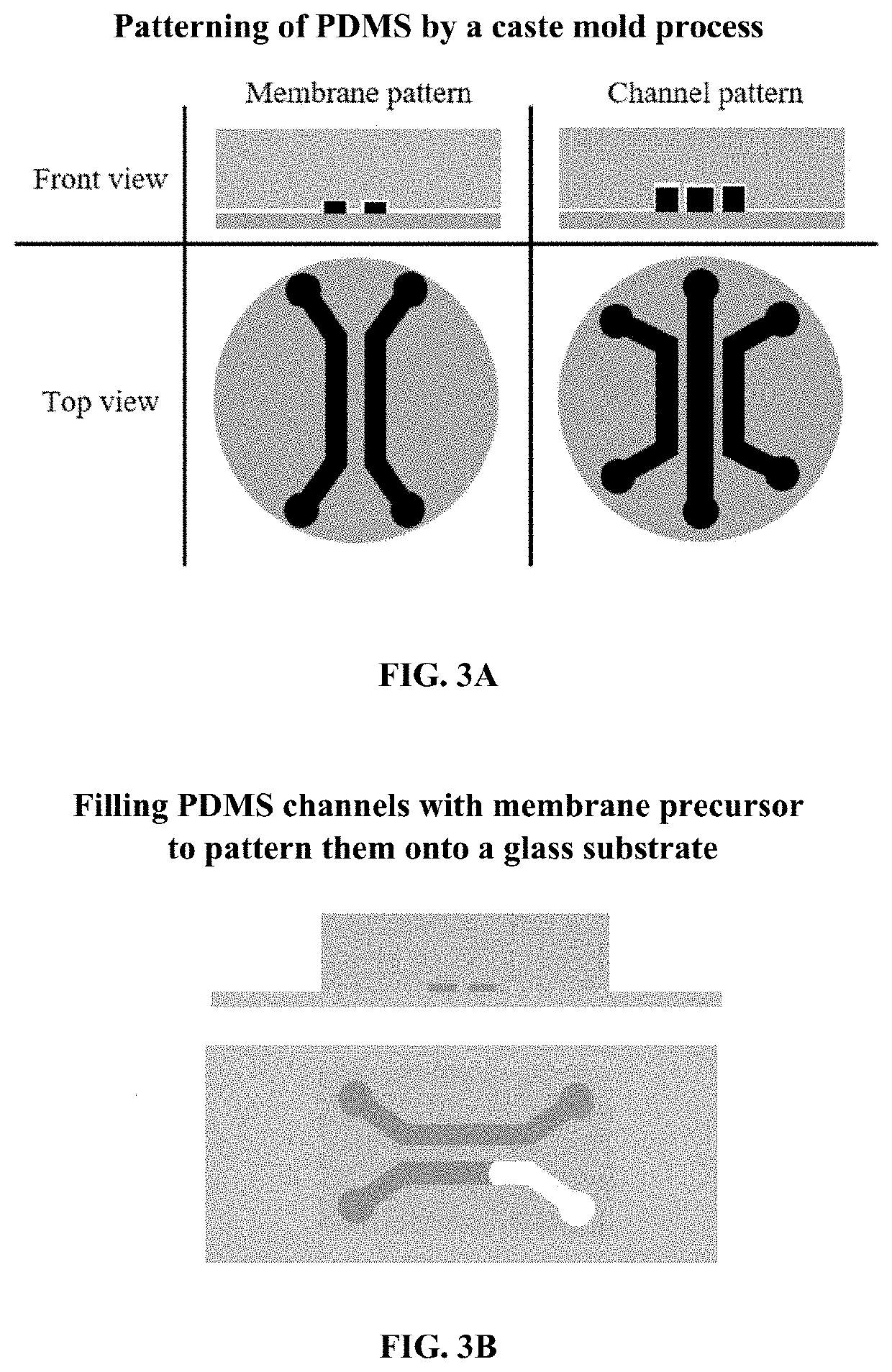
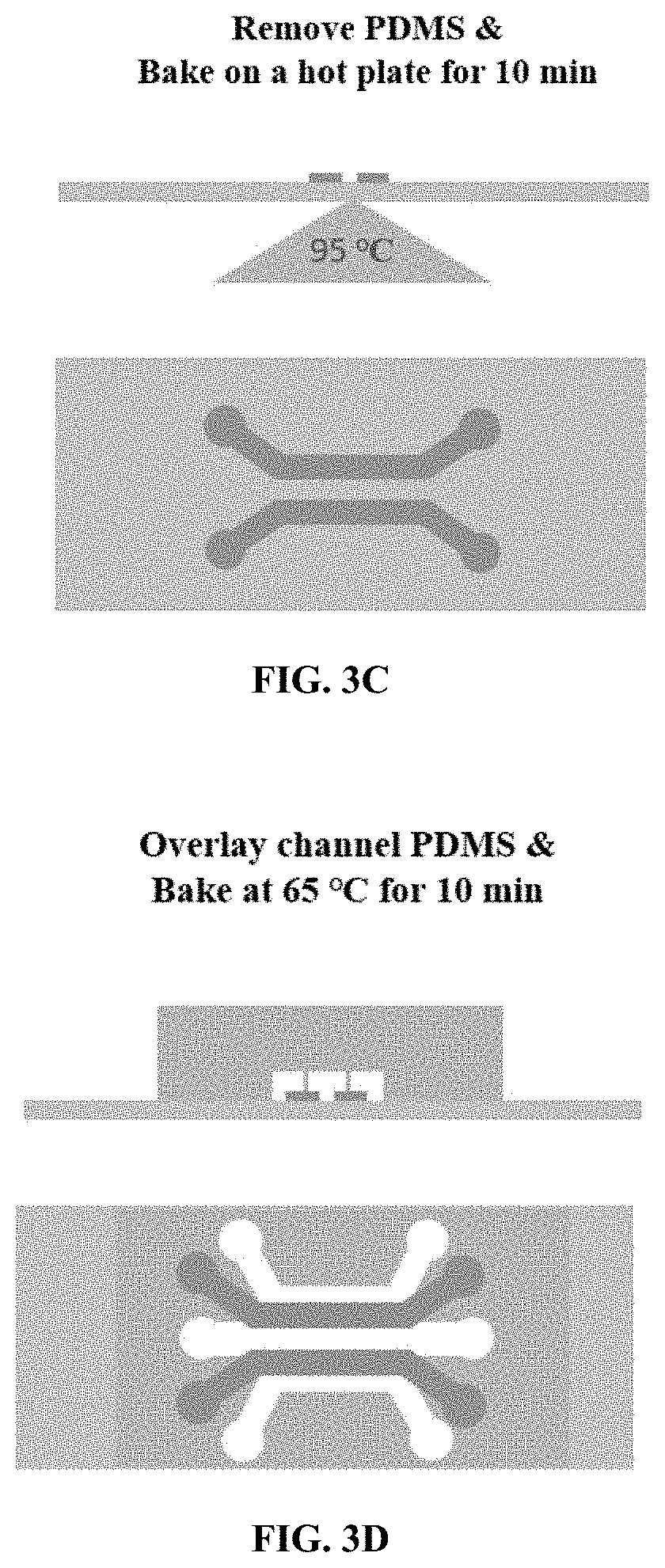
Image

Examples
example 1
Standing Droplet Electrokinetics
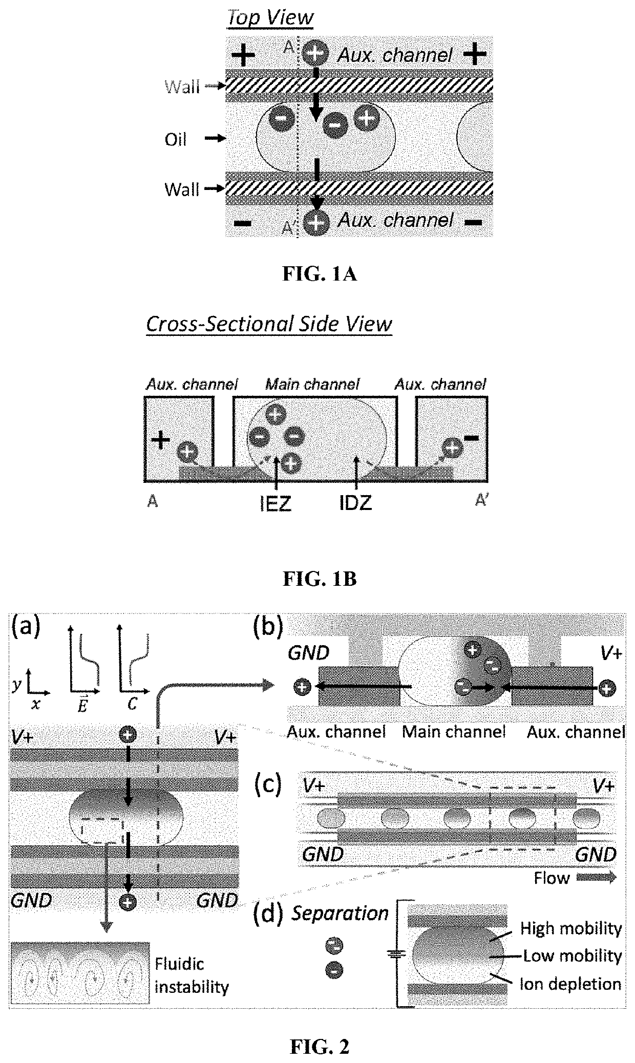
[0173]In this Example, the electrokinetics of charged species in standing droplets was investigated.
[0174]The device used in this Example was prepared as described above. Droplets comprising 10.0 mM phosphate buffer and 10.0 μM BODIPY2−, were inserted into the main channel. 15.0 V was applied to the reservoirs of the anodic auxiliary channel (“V+”), and ground to the cathodic auxiliary channel (“GND”). Once the voltage bias was applied, a gradient in the fluorescence intensity was observed to develop across the droplet as indicated in FIGS. 5A, 5B and 5C. FIG. 5A is at t=0 seconds and the images in FIGS. 5B and 5C are 2 and 5 seconds after application of the voltage, respectively. The concentration gradient results from cation selective ionic current through the membranes contacting the droplet, which leads to high concentration, the IEZ, adjacent to the anodic membrane and depletion, the IDZ, at the cathodic end demonstrating that there is ionic comm...
example 2
Conservation of Mass in Droplets
[0179]In this Example, the integral of fluorescence intensity across the entire area of the droplet was monitored over time to verify conservation of the fluorophore in the droplet.
[0180]The device used in this Example was prepared as described above. The W / O interface and cation selective membrane isolate anionic analytes inside the droplet, allowing enrichment without loss of analyte. The variation in integrated fluorescence intensity across the droplet, δt, was evaluated using Formula I wherein It, I0, and ΩD are the local intensity at time t, the local intensity at time t=0 seconds, and the projected area of the droplet in the image. Subscript i represents the pixel index.
δt=∫ΩDIt∂ΩD-∫ΩDI0∂ΩD∫ΩDI0∂ΩD≈∑i∈ΩDIt,i-∑i∈ΩDI0,i∑i∈ΩDI0,i(I)
[0181]FIGS. 4A, 4B, 4C, and 4D show the maximum δt, expressed as a percentage, at several voltage biases, for several trials with stationary droplet. FIG. 4A shows the data for trials with 22.3 nL droplet and 1....
example 3
Impact of Electrolyte Concentration, Applied Voltage, and Droplet Size
[0182]In this Example, the impact of electrolyte concentration, magnitude of the applied voltage bias, and droplet size on the concentration distribution of the anionic fluorophore in standing droplets was investigated.
[0183]The device used in this Example was prepared as described above. In this Example, two buffer concentrations, 1.0 mM and 10.0 mM phosphate buffer were evaluated, as well as droplets each with a distinct volume, over a range of voltages from 1.0 V to 15.0 V. At each condition, the ICP experiment was performed three times.
[0184]FIG. 13A shows the temporal evolution of EF plotted as an ensemble average for each trial. In all cases, there is an initial rapid increase in EF from t=0 to 5 seconds, which then approaches a limiting value. The limiting EF and enrichment rate are positively correlated to voltage bias and negatively correlated to ionic strength. In FIG. 13B, the maximum EF, plotted as a f...
PUM
 Abstract
Description
Claims
Application Information