Laser apparatus, laser processing system, and method for manufacturing electronic device

Pending Publication Date: 2022-04-28
GIGAPHOTON
View PDF0 Cites 0 Cited by
  • Summary
  • Abstract
  • Description
  • Claims
  • Application Information

AI Technical Summary

Benefits of technology

The present invention relates to a laser apparatus and a method for manufacturing an electronic device using a plurality of semiconductor lasers, optical switches, a wavelength conversion system, an ArF excimer laser amplifier, and a controller. The laser beams outputted from the semiconductor lasers have different wavelengths, which are converted by the wavelength conversion system to generate wavelength-converted beams. The apparatus is designed to output laser beams that have wavelengths that differ from an optical absorption line of oxygen, which is important for excimer laser amplification. The method involves irradiating a radiation receiving object with the laser beams to manufacture an electronic device. The technical benefits of this invention include improved laser beam quality, reduced laser beam distortion, and improved electronic device manufacturing efficiency.

Problems solved by technology

A projection lens made of a material that transmits ultraviolet light, such as KrF and ArF laser beams, therefore produces chromatic aberrations in some cases.
As a result, the resolution of the projection lens may decrease.

Method used


Image

  • Laser apparatus, laser processing system, and method for manufacturing electronic device
  • Laser apparatus, laser processing system, and method for manufacturing electronic device
  • Laser apparatus, laser processing system, and method for manufacturing electronic device

Examples


first embodiment

2. First Embodiment

2.1 Configuration

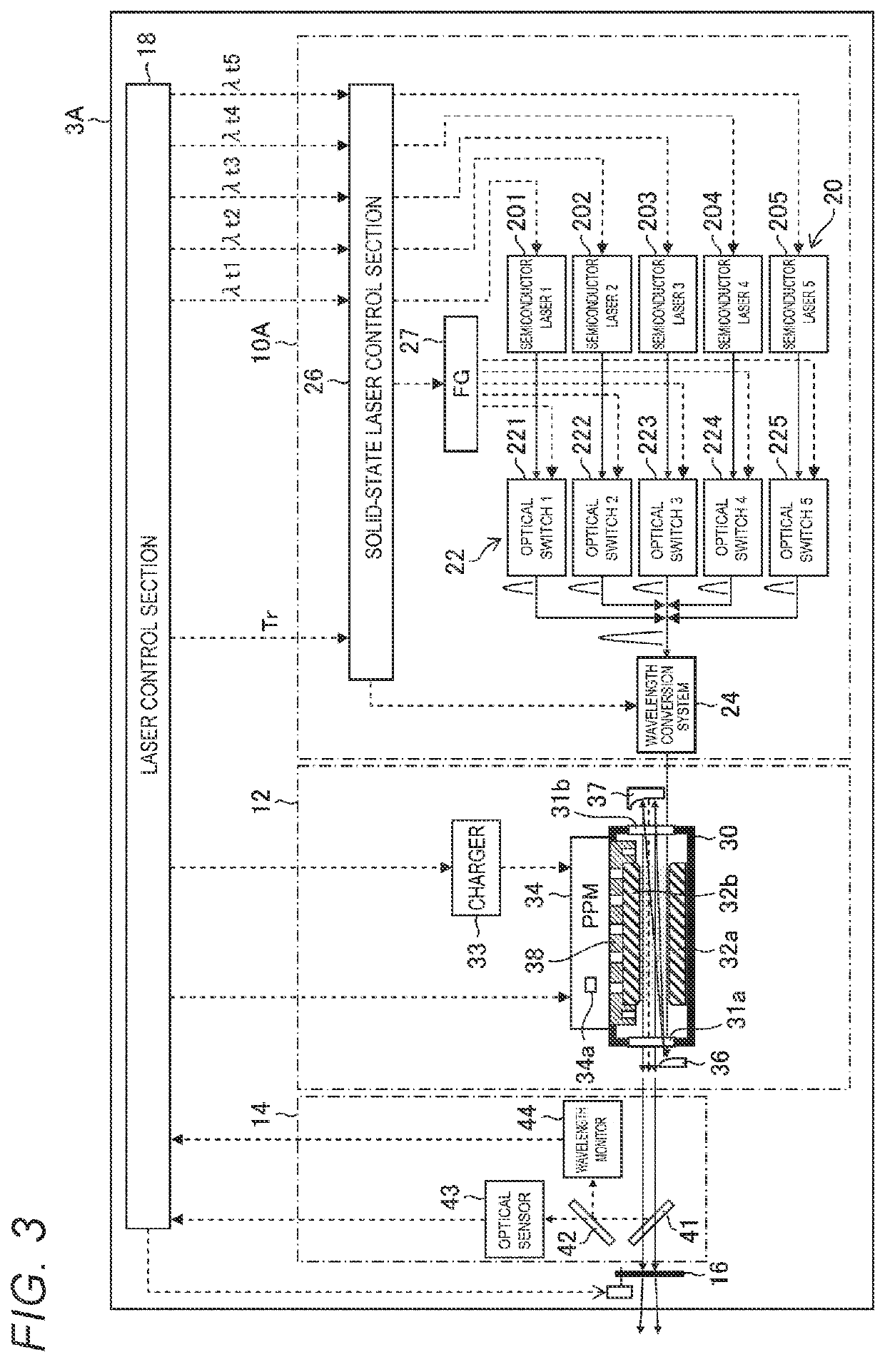
[0098]FIG. 3 schematically shows the configuration of a laser apparatus 3A according to a first embodiment. In the first embodiment, the laser apparatus 3A shown in FIG. 3 is used in place of the laser apparatus 3 described with reference to FIG. 1. The configuration shown in FIG. 3 will be described in terms of differences from the laser apparatus 3 shown in FIG. 1.

[0099]The laser apparatus 3A shown in FIG. 3 is a wavelength-tunable multiline ArF excimer laser apparatus including a wavelength-tunable multiline solid-state laser system 10A. In the present specification, the term “multiline” refers to a spectrum representing the distribution of optical intensity on a wavelength basis and having a plurality of peak wavelengths, and “multiline” is also called a “multiline spectrum”. The term “multiline” also means in some cases a laser beam having a multiline spectrum.

[0100]The wavelength-tunable multiline solid-state laser system 10A includes a plur...

second embodiment

3. Second Embodiment

3.1 Configuration

[0131]FIG. 6 schematically shows the configuration of a laser apparatus 3B according to a second embodiment. In the second embodiment, the laser apparatus 3B shown in FIG. 6 is used in place of the laser apparatus 3A described with reference to FIG. 3. The configuration shown in FIG. 6 will be described in terms of differences from the laser apparatus 3A shown in FIG. 3. The description of the second embodiment will be made of a case where the spectral linewidth of the pulsed laser beam outputted by the laser apparatus 3B is further widened to a value greater than 200 pm, as compared with the first embodiment.

[0132]The laser apparatus 3B shown in FIG. 6 is a wavelength-tunable multiline ArF excimer laser apparatus including a wavelength-tunable multiline solid-state laser system 10B.

[0133]The wavelength-tunable multiline solid-state laser system 10B includes a plurality of semiconductor lasers 201 to 203, a plurality of optical switches 221 to 22...


PUM

PropertyMeasurementUnit
Wavelengthaaaaaaaaaa

Abstract

A laser apparatus according to an aspect of the present disclosure includes a plurality of semiconductor lasers, a plurality of optical switches disposed in the optical paths of the plurality of respective semiconductor lasers, a wavelength conversion system configured to convert pulsed beams outputted from the plurality of optical switches in terms of wavelength to generate wavelength-converted beams, an ArF excimer laser amplifier configured to amplify the wavelength-converted beams, and a controller configured to control the operations of the plurality of semiconductor lasers and the plurality of optical switches, and the plurality of semiconductor lasers are each configured to output a laser beam so produced that wavelengths of the wavelength-converted beams are wavelengths at which the ArF excimer laser amplifier performs amplification and differ from the optical absorption lines of oxygen.

Description

CROSS-REFERENCE TO RELATED APPLICATIONS[0001]The present application is a continuation application of International Application No. PCT / JP2019 / 034236, filed on Aug. 30, 2019, the entire contents of which are hereby incorporated by reference.BACKGROUND1. Technical Field[0002]The present disclosure relates to a laser apparatus, a laser processing system, and a method for manufacturing an electronic device.2. Related Art[0003]In recent years, a semiconductor exposure apparatus is required to improve the resolution thereof as semiconductor integrated circuits are increasingly miniaturized and highly integrated. To this end, reduction in the wavelength of the light outputted from a light source for exposure is underway. For example, a KrF excimer laser apparatus, which outputs a laser beam having a wavelength of about 248 nm, and an ArF excimer laser apparatus, which outputs a laser beam having a wavelength of about 193 nm, are used as a gas laser apparatus for exposure.[0004]The beam fr...

Claims


Application Information

Patent Timeline
IPC IPC(8): H01S3/10H01S3/225H01S5/40H01S5/00H01S3/23H01S5/12G02F1/35H01S3/16H01S3/067B23K26/06
CPCH01S3/10092B23K26/0643H01S5/4025H01S5/0092H01S3/2366H01S5/12G02F1/354H01S3/1625H01S3/1636H01S3/06754G02F1/3507H01S3/06716H01S3/1618H01S3/1608H01S3/2251H01S3/2375H01S3/2308H01S5/0085H01S5/4012H01S5/0687H01S5/4087H01S3/06758H01S3/0092
Inventor SUZUKI, AKIYOSHIIGARASHI, HIRONORI
Owner GIGAPHOTON
Why Eureka
Try Eureka