Liquid cooling module and electronic device including the same

a technology of liquid cooling module and electronic device, which is applied in the direction of electrical equipment, electrical apparatus, electrical apparatus contruction details, etc., can solve the problems of working fluid leakage, difficult to reduce the space occupied by the whole liquid cooling system, and difficult to reduce the space occupied by the liquid cooling system, etc., to achieve the effect of increasing the yield of formation, facilitating the passage of components through the intercommunicating port, and increasing the flow efficiency of working fluid driven by the pump

Pending Publication Date: 2022-05-12
SUNONWEALTH ELECTRIC MACHINE IND
View PDF0 Cites 0 Cited by
  • Summary
  • Abstract
  • Description
  • Claims
  • Application Information

AI Technical Summary

Benefits of technology

[0029]In an example, the plurality of ribs does not extend to a portion of the first chamber surrounding the intercommunicating port and a portion of the second chamber surrounding the intercommunicating port. Thus, the working fluid can be gathered at a location adjacent to the intercommunicating port to pass through the intercommunicating port more smoothly, increasing the flow efficiency of the working fluid driven by the pump.
[0030]In an example, the stator and the impeller are disposed on the same side of the partitioning board. Thus, the other side of the partitioning board can be further thinned, which is helpful in development of thinning of the housing.
[0031]In an example, the first chamber and the second chamber of the housing are formed by etching, increasing the yield of formation and assisting in thinning development.
[0032]In an example, the working fluid is an electrically non-conductive liquid. Thus, the stator of the pump does not require additional waterproof structure, simplifying the structure of the liquid cooling module to thereby increase the manufacturing convenience.

Problems solved by technology

However, the conventional liquid cooling system 9 has many components, and assembly of the components requires a certain space.
Thus, it is difficult to reduce the space occupied by the whole liquid cooling system 9, which is a common issue to a thinned electronic device in spatial arrangement.
Furthermore, leakage of the working fluid could occur when the piping assembly 94 of the conventional liquid cooling system 9 is not sealingly assembled with the associated components.
Thus, assembly must be carried out cautiously, which is relatively troublesome and time-consuming Furthermore, the more components of the piping assembly 94, the more likely the occurrence of leakage.
Moreover, after a period of time of use, the piping assembly 94 could have problems including evaporation of working fluid, aging and breakage of pipes, etc.

Method used


Image

  • Liquid cooling module and electronic device including the same
  • Liquid cooling module and electronic device including the same
  • Liquid cooling module and electronic device including the same

Examples


first embodiment

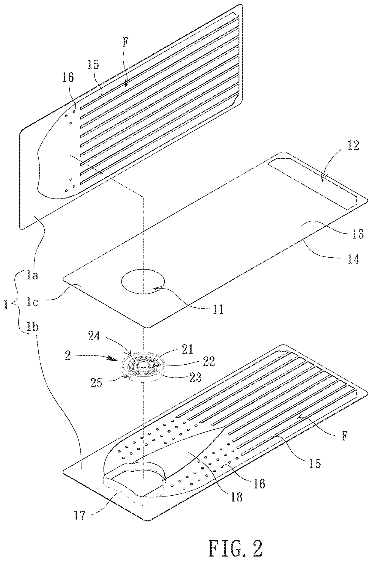
[0046]With reference to FIGS. 2 and 6, a liquid cooling module of a first embodiment according to the present invention includes a housing 1 and a pump 2. The pump 2 is received in the housing 1 and can be used to drive a working fluid L to circulate in the housing 1.

[0047]The housing 1 can be made of copper, aluminum, titanium, stainless steel or other thermally conductive material. The housing 1 includes first and second chambers S1 and S2 therein. The first chamber S1 and the second chamber S2 are filled with the working fluid L and intercommunicate with each other via an intercommunicating port 11 and a backflow port 12. Thus, operation of the pump 2 drives the working fluid L to flow from the first chamber S1 through the intercommunicating port 11 into the second chamber S2. Then, the working fluid L flows through the backflow port 12 back into the first chamber S1. Thus, the working fluid L can circulate in the first chamber S1 and the second chamber S2 or circulate in a rever...

second embodiment

[0060]FIG. 8 shows a liquid cooling module of a second embodiment according to the present invention. In this embodiment, the pump 2 may optionally exclude the seat 23 (shown in FIG. 6) for further simplification of the pump 2.

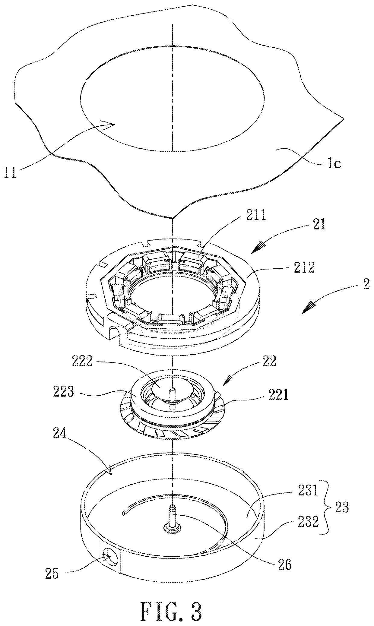
[0061]More specifically, the pump 2 of this embodiment may optionally be directly coupled to the partitioning board 1c by the stator 21, and a portion of the stator 21 surrounding the intercommunicating port 11 forms the liquid inlet 24 of the pump 2. Furthermore, the shaft coupling portion 26 of the pump 2 can be directly disposed in the bulge 17 of the housing 1. The impeller 22 is rotatably coupled to the shaft coupling portion 26. Thus, the working fluid L flowing from the first chamber S1 through the intercommunicating port 11 can entirely pass through the liquid inlet 24 and flow through the stator 21 and the impeller 22 into the fluid passages F in the second chamber S2 (see also FIG. 2). The pump 2 of this embodiment has a simpler structure to assist i...

third embodiment

[0062]FIGS. 9 and 10 show a liquid cooling module of a third embodiment according to the present invention. In this embodiment, the bulge 17 of the second board 1b may optionally be formed by assembly, providing a pump 2 of another type.

[0063]More specifically, in this embodiment, a through-hole 19 is provided on the second board 1b in the form of a sheet. Furthermore, a cap P is coupled to an outer face of the second board 1b and is aligned with the through-hole 19, such that the cap P forms the bulge 17 of the second board 1b. Thus, at least a portion of the pump 2 is received in the bulge 17. As a result, when the specification of the pump 2 changes, only a change of the mold for forming the cap P is required. The mold for forming the second board 1b is still applicable, reducing the mold costs at the manufacturing end. The cap P may optionally be coupled to the second board 1b by laser welding, such that the sealing effect therebetween is excellent and that no gaps exist therebe...


PUM


Abstract

A liquid cooling module includes a housing having first and second chambers filled with a working fluid and intercommunicating with each other via an intercommunicating port and a backflow port. A pump is received in the housing and is aligned with the intercommunicating port. The pump includes a stator driving an impeller to rotate, driving the working fluid to flow from the first chamber through the intercommunicating port, the stator, and the impeller. The working fluid flows through the second chamber back into the first chamber via the backflow port. An electronic device includes a casing, an electric module received in the casing and including a heat generating area, and the liquid cooling module. The liquid cooling module is disposed in the casing and is in thermal connection with the heat generating area via a heat absorbing zone of the housing aligned with the first chamber or the second chamber.

Description

CROSS REFERENCE TO RELATED APPLICATION[0001]The application claims the benefit of Taiwan application serial No. 109138862, filed on Nov. 6, 2020, and the entire contents of which are incorporated herein by reference.BACKGROUND OF THE INVENTION1. Field of the Invention[0002]The present invention relates to a cooling module and an electronic device and, more particularly, to a liquid cooling module capable of maintaining an electronic device at a suitable working temperature and an electronic device including the liquid cooling module.2. Description of the Related Art[0003]FIG. 1 shows a conventional liquid cooling system 9 including a heat absorbing unit 91, a cooling unit 92, a pump 93, and a piping assembly 94. The heat absorbing unit 91 can abut a heat source Z of an electronic device. The piping assembly 94 includes a pipe 941 intercommunicating the pump 93 and the heat absorbing unit 91, a pipe 942 intercommunicating the pump 93 and the cooling unit 92, and a pipe 943 intercommu...

Claims


Application Information

Patent Timeline
Patent Type & Authority Applications(United States)
IPC IPC(8): H05K7/20
CPCH05K7/20272H05K7/20218H05K7/20136H05K7/20254H05K7/20263
Inventor HORNG, ALEXYIN, TSO-KUOLI, MING-TSUNG
Owner SUNONWEALTH ELECTRIC MACHINE IND
Why Eureka
Try Eureka