Mechanical Breaking and Fusing Combined Multi-Fracture Excitation Fuse

a fuse and multi-fracture technology, applied in the field of fuse, can solve the problems of high temperature, high working current, high temperature, etc., and achieve the effects of reducing temperature rise and power consumption, small current-carrying ability, and improving resistance to current impa

Active Publication Date: 2022-06-16
XIAN ZHONGRONG ELECTRIC CO LTD
View PDF10 Cites 0 Cited by
  • Summary
  • Abstract
  • Description
  • Claims
  • Application Information

AI Technical Summary

Benefits of technology

[0006]The technical problem to be solved by the present disclosure is to provide a fuse that breaks a conductor through combination of fusing and mechanical force, and the fuse is made to be connected in parallel to some fractures and under certain conditions, be connected in series with some fractures, by utilizing the ability of the fuse reliably breaking large-amplitude current and through integrated design, so that the fuse is connected in parallel with the conductor to reduce the temperature rise and power consumption in a non-breaking state and improve the resistance to current impact, wherein the fuse only needs a small current-carrying ability. When a breaking action is required, the fuse greatly reduces, by making an exciter and a breaking device break a portion of the conductor, the arc energy of the fracture connected in parallel therewith, protects the parallelly-connected fractures to safely restore the insulation dielectric performance under large current, and the fuse is connected in series to some fractures, so that the energy value of arc passing through the serially-connected fractures is limited to protect the fractures to safely break a certain amplitude of overcurrent without the exceeding a safety limit; and utilizing the linkage of breaking device can control the sequence of the breaking actions (i.e. forming sequence of the fractures), and the fuse can be flexibly used to protect the serially-connected fractures and parallelly-connected fractures, improving the ability of breaking large-amplitude overcurrent and enabling rapidly breaking of amplitude overcurrent of small current, thus realizing fast and reliable breaking of all overcurrent from zero to maximum breaking capability, greatly reducing volume and saving costs.

Problems solved by technology

The fuse used for circuit overcurrent protection is fused based on the heat generated by the current flowing through the fuse, the existing main problem is that it is restricted by the following working principle: because the heat generated by the continuous flowing of a certain amplitude of current causes the melt inside the fuse to heat up and reach the melting temperature or vaporization temperature, the melt is fused to form a fracture.
If the current value is not large enough or the duration is not long enough, the temperature of the melt cannot reach the melting point, the melt cannot be fused to be broken, and the circuit cannot be cut off, but a certain degree of high temperature will occur.
Under different working conditions, the requirements for the current-flowing and heating of the melt are opposite, wherein if the heating power is reduced or the degree of concentration of the melt current heating distribution is reduced, the fuse cannot break a certain amplitude of fault current at a sufficiently fast breaking speed; and conversely, if the fault current with a certain amplitude can be broken at a sufficiently fast breaking speed to increase the thermal power of the fuse and the degree of concentration of the melt heat distribution, it is difficult to carry a higher working current and has a higher temperature rise and power consumption, or it is difficult to withstand the cyclic impact of a larger overload / impulse current without being damaged, and it requires better heat dissipation conditions, larger volume and higher cost.
For example, in the main circuit of a new energy vehicle, if there is a low-amplitude overload or short-circuit current, a traditional fuse with a small rated current specification cannot meet the requirements of normal load current and non-breaking due to excessive current for a short time, and if the traditional fuse with a large rated current specification is selected, it cannot meet the requirement of a sufficiently fast breaking speed.
When the battery pack of a new energy vehicle is low in power, the output current amplitude is not large during short circuit, wherein if the fuse cannot be fused to be broken quickly in time, it may cause the arc at the short-circuit point to last too long, which may cause fire burning, or the battery pack may continue to heat up due to excessive current and cause damage or fire-burning.
In addition, the fuse based on hot-melt principle cannot communicate with the external equipment, and cannot be triggered by other signals except the current, and cannot cut off the circuit to achieve protection, if the vehicle is in a serious collision, soaking in water, or the battery temperature is too high after exposure to the sun and the like.
However, there are some serious shortcomings and defects: the current flowing through the fracture arcs in the air, it is difficult to extinguish a large-amplitude fault current arc, or a large space is required; air is used to cool and break the arc, and its extinguishing is greatly affected by air pressure, temperature and humidity, air impurities and the like, and its reliability is not good; during the breaking process, the arc directly burns the piston head, and the burning damage will affect the smooth arc extinguishing; and if the large-amplitude current arc is extinguished by air in a small-volume space, the insulation resistance after disconnection is also relatively low.

Method used


Image

  • Mechanical Breaking and Fusing Combined Multi-Fracture Excitation Fuse
  • Mechanical Breaking and Fusing Combined Multi-Fracture Excitation Fuse
  • Mechanical Breaking and Fusing Combined Multi-Fracture Excitation Fuse

Examples


Embodiment Construction

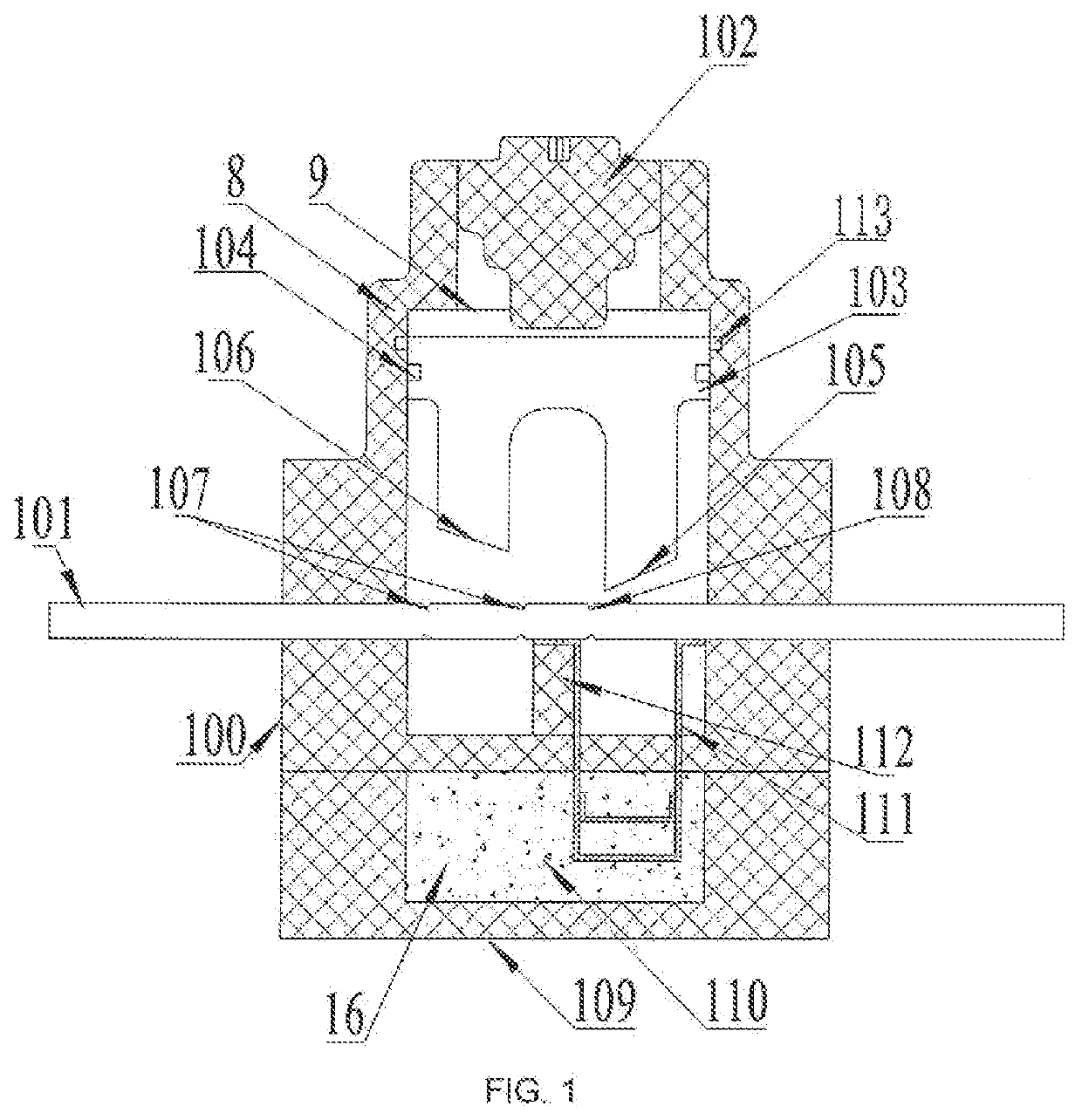
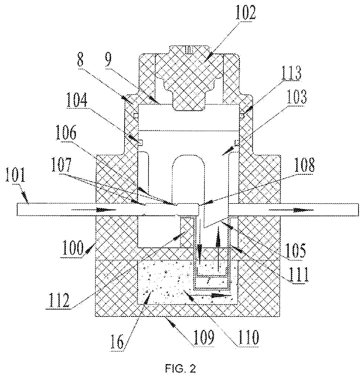
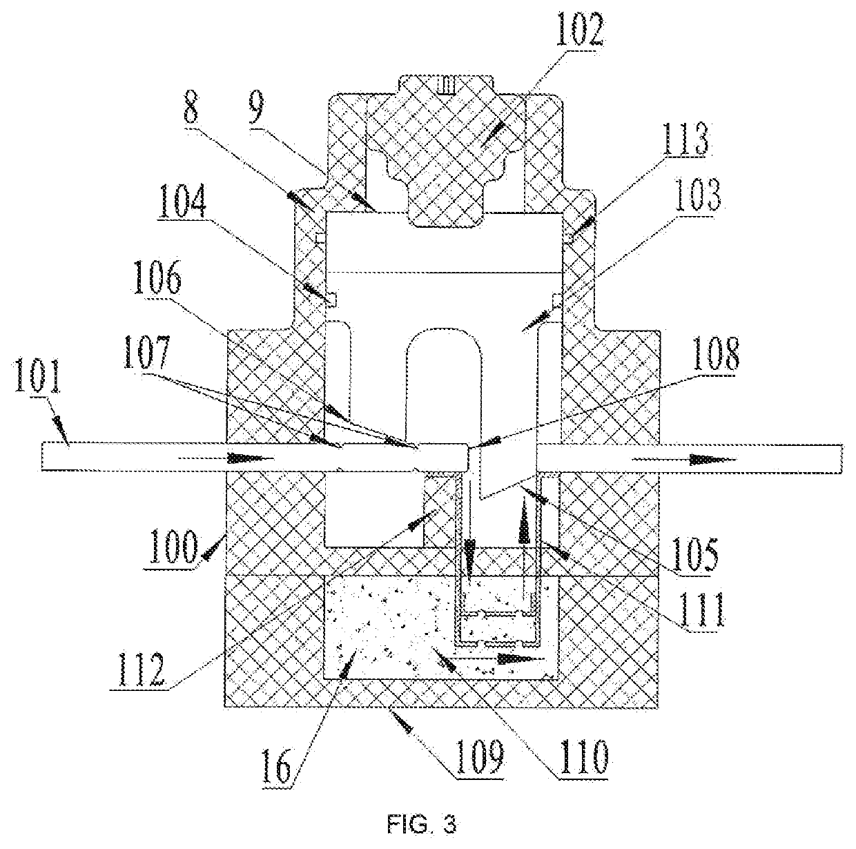
[0035]Hereinafter, the embodiments will be described in detail with reference to the drawings. As shown in FIG. 1 to FIG. 7, the excitation fuse (also referred to a trigger fuse) of the present disclosure mainly includes a shell 100, a conductor 101, an excitation device (also referred to as a trigger device) 102, and a breaking device 103.

[0036]The shell 100 has a mold cavity penetrating through the upper end of the shell 100. The conductor 101 is inserted into the shell 100, and the conductor 101 passes through the mold cavity provided in the shell 100 to divide the mold cavity into two parts. The two ends of the conductor 101 extend out of the shell 100 and can be connected to an external circuit. The conductor 101 can also be arranged inside the shell 100, and has two ends connected respectively with conductive terminals which are arranged at two ends of the shell 100 and extend out of outside of the shell 100, and are connected to an external circuit through the conductive term...


PUM


Abstract

A mechanical breaking and fusing combined multi-fracture excitation fuse includes a shell, wherein a cavity is formed in the shell, and at least one conductor penetrates through the shell and penetrates through the cavity; at least one excitation device and one breaking device are arranged in the cavity of the shell; the excitation device can receive an external excitation signal to drive the breaking device to act to break a conductor corresponding thereof to form at least two fractures on the conductor, at least one fuse is connected in parallel onto the conductor. The melt is connected in parallel with at least one fracture, and the melt is connected in series with at least one fracture.

Description

CROSS-REFERENCE TO RELATED APPLICATION[0001]The present disclosure claims priority of Chinese patent application with the filing number 202011458693.0 filed on Dec. 11, 2020 with the Chinese Patent Office, and entitled “Mechanical breaking and fusing combined multi-fracture excitation fuse”, the contents of which are incorporated herein by reference in entirety.TECHNICAL FIELD[0002]The present disclosure relates to the fields of power protection, control, and electric vehicles, in particular to a fuse for controlling and cutting off a current transmission circuit through an external signal.BACKGROUND ART[0003]The fuse used for circuit overcurrent protection is fused based on the heat generated by the current flowing through the fuse, the existing main problem is that it is restricted by the following working principle: because the heat generated by the continuous flowing of a certain amplitude of current causes the melt inside the fuse to heat up and reach the melting temperature or...

Claims


Application Information

Patent Timeline
Patent Type & Authority Applications(United States)
IPC IPC(8): H01H71/14H01H85/38H01H85/08
CPCH01H71/14H01H2071/147H01H85/08H01H85/38H01H71/121H01H85/0039H01H85/05H01H85/055H01H85/175H01H39/006H01H85/10H01H85/12H01H39/00
Inventor SHI, XIAOGUANGCHEN, RONGRONGWANG, WEI
Owner XIAN ZHONGRONG ELECTRIC CO LTD
Why Eureka
Try Eureka