Gating camera

a gating camera and camera body technology, applied in the field of gating cameras, can solve the problems of difficult to recognize objects, difficult to separate individual objects, and typical monocular cameras are not capable of acquiring depth information, so as to reduce the effect of active sensors and shorten the image capture time of gating cameras

Pending Publication Date: 2022-07-07
KOITO MFG CO LTD
View PDF0 Cites 0 Cited by
  • Summary
  • Abstract
  • Description
  • Claims
  • Application Information

AI Technical Summary

Benefits of technology

[0036]With an embodiment, this is capable of generating an image including an entire object of interest with image capture ranges having a reduced depth. With an embodiment, this allows the image capture time of the gating camera to be shortened. With an embodiment, this is capable of reducing the effects of the active sensors in the vicinity.

Problems solved by technology

Typical monocular cameras are not capable of acquiring depth information.
Accordingly, in a case in which there is overlap between multiple objects positioned at different distances, it is difficult to separate individual objects.
Accordingly, it is difficult to recognize what the object is based on the individual slice images IMGs.
However, in a case in which the depth of the image capture range is excessively increased, there is a high probability that there will be a range including an object that differs from the object of interest.
This degrades the advantage of the gating camera.
2. With such a gating camera, the image transmission rate from an image sensor to an image processing unit becomes a bottleneck.
However, the time required for the gating camera to generate slice images for all the image capture ranges (which will be referred to as the “image capture time of the gating camera”) is limited by the transmission rate.
In a case in which there is a pulsed light source that emits light having the same wavelength as that provided by the illumination apparatus of the active sensor at a cycle that is an integer multiple or an integer fraction of the light-emission cycle of the active sensor, this drastically degrades the detection precision of the active sensor.
Furthermore, this outline is not an extensive overview of all conceivable embodiments, and is by no means intended to restrict essential elements of the embodiments.
In this case, in a case in which such a cropping region is determined at a given time point as a reference, there is high probability that such an object will deviate from the cropping region after the cropping region is determined.
In this case, such an object remains in the cropping region for a long period of time.
Furthermore, there is a high probability that such an object at a far distance appears in a concentrated manner in the vicinity of the vanishing point.
Accordingly, a single exposure is insufficient for generating a slice image having sufficient brightness.

Method used


Image

  • Gating camera
  • Gating camera
  • Gating camera

Examples


embodiment 1

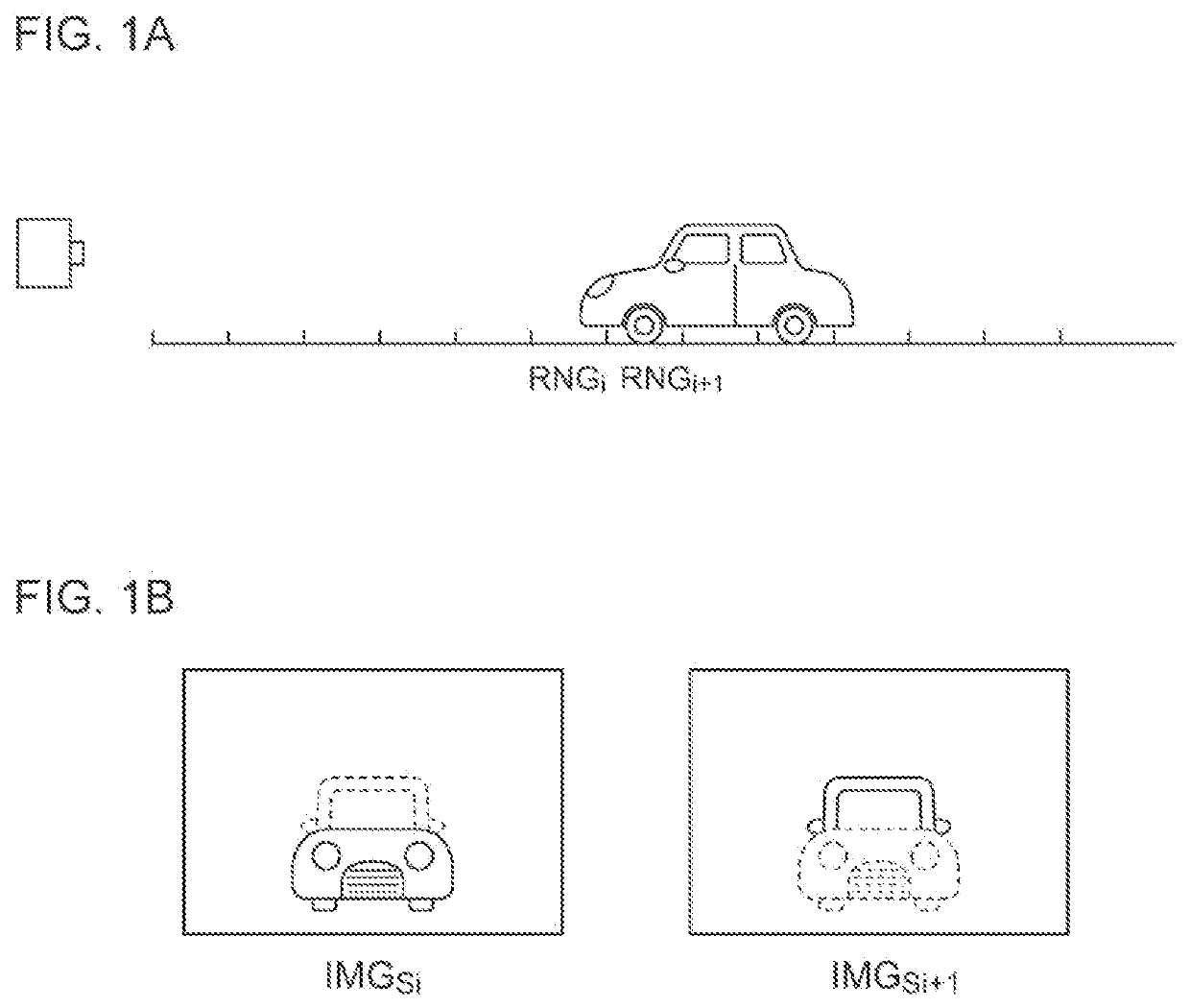
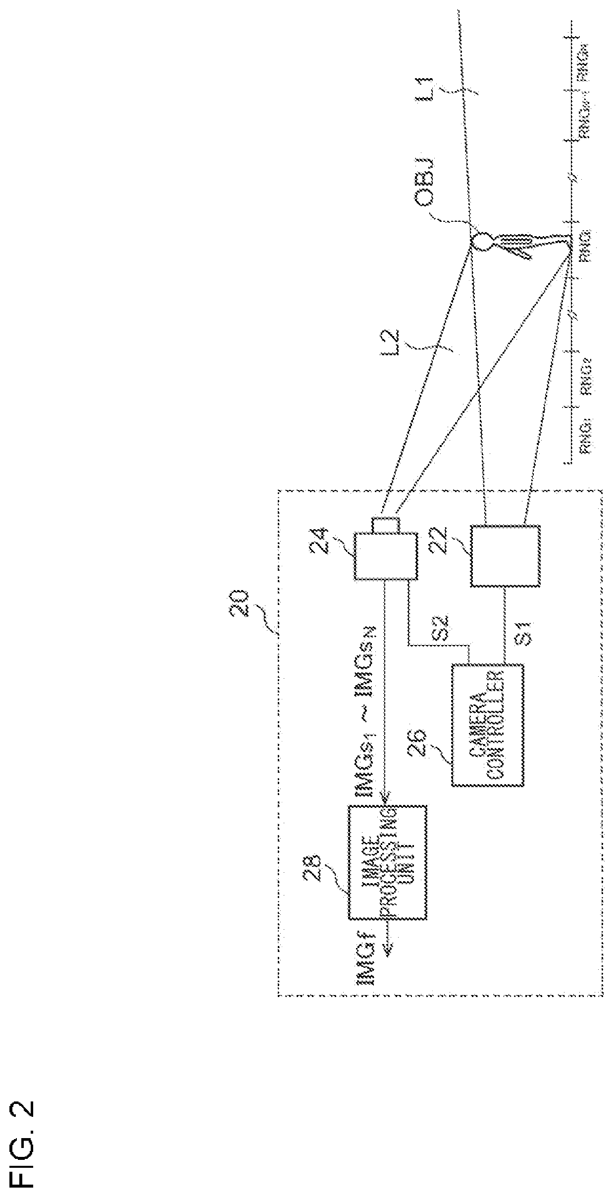
[0065]FIG. 2 is a block diagram showing a gating camera 20 according to an embodiment 1. The gating camera 20 captures images for a plurality of N (N≥2) ranges RNG1 through RNGN divided in the depth direction. For example, the depth of a single image capture range is designed on the order of 1 to 2 m (e.g., 1.5 m). Description will be made assuming that N=100.

[0066]The gating camera 20 includes an illumination apparatus 22, an image sensor 24, a camera controller 26, and an image processing unit 28.

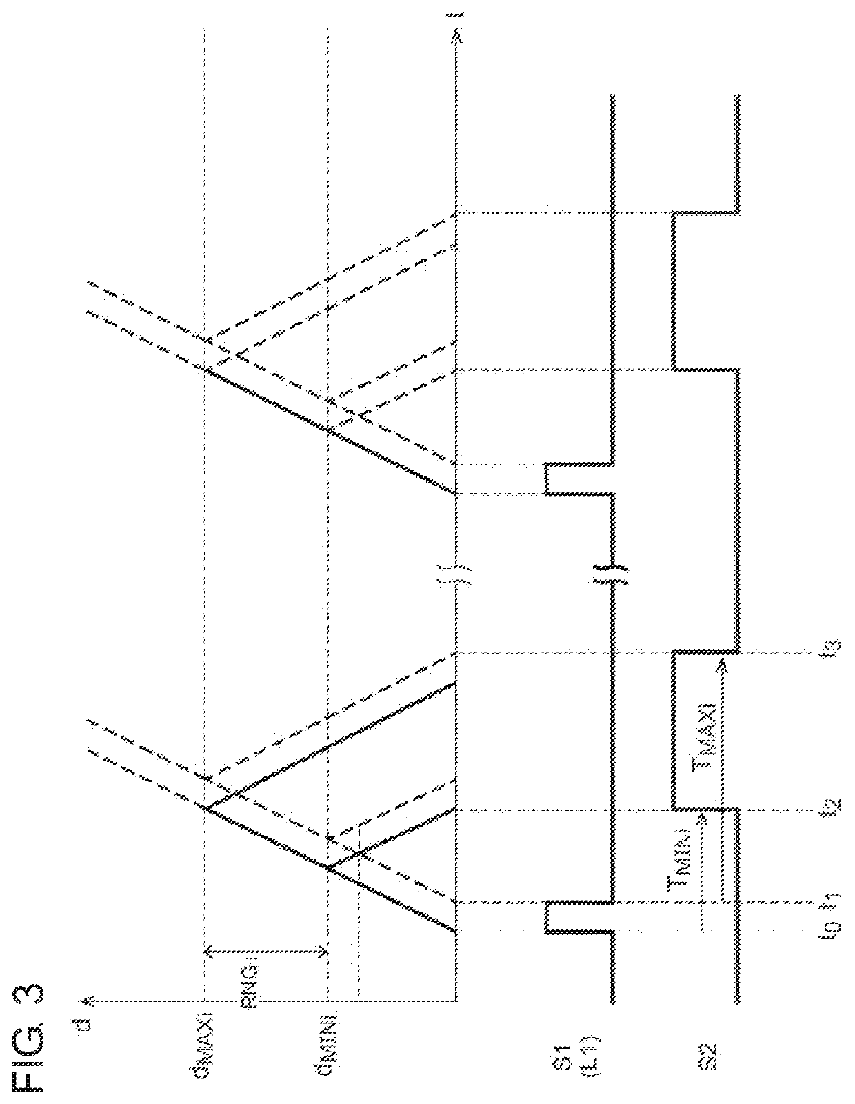
[0067]The illumination apparatus 22 illuminates probe light L1 in front of the vehicle in synchronization with a light emission timing signal S1 supplied from the camera controller 26. The probe light L1 is preferably generated as infrared light. However, the present invention is not restricted to such an arrangement. Also, the probe light L1 may be visible light having a predetermined wavelength.

[0068]The image sensor 24 is configured to support exposure control in synchronization with a...

embodiment 2

[0095]FIG. 10 is a block diagram showing a gating camera 20 according to an embodiment 2. The gating camera 20 captures images for a plurality of N (N≥2) ranges RNG1 through RNGN divided in the depth direction. For example, the depth d of a single image capture range is designed on the order of 1 to 2 m (e.g., 1.5 m). Description will be made assuming that N=100.

[0096]The gating camera 20 includes an illumination apparatus 22, an image sensor 24, a camera controller 32, and an image processing unit 34.

[0097]The illumination apparatus 22 illuminates probe light L1 in front of the vehicle in synchronization with a light emission timing signal S1 supplied from the camera controller 32. The probe light L1 is preferably generated as infrared light. However, the present invention is not restricted to such an arrangement. Also, the probe light L1 may be visible light having a predetermined wavelength.

[0098]The image sensor 24 is configured to support exposure control in synchronization wit...

embodiment 3

[0135]FIG. 16 is a block diagram showing a gating camera 20A according to an embodiment 3. In the gating camera 20A, the illumination apparatus 22 is configured to focus or diffuse the probe light L1 so as to provide a variable illumination range. The camera controller 32 is configured to be capable of adaptively controlling the illumination range of the illumination apparatus 22 according to a control signal S4.

[0136]When the slice images IMGs to be cropped and transmitted are captured, the camera controller 32 instructs the illumination apparatus 22 to focus the probe light L1 so as to narrow the illumination range.

[0137]For example, when the far-distance slice image group through IMGsN is to be captured in the second mode, the camera controller 32 focuses the probe light L1 so as to illuminate the probe light L1 in a concentrated manner to the region of interest. This allows the illuminance of the illumination range to be raised, thereby allowing a clear image to be acquired.

[013...


PUM


Abstract

An illumination apparatus illuminates probe light. A gating camera captures an image for each of image capture ranges divided in the depth direction. A camera controller controls a timing at which the illumination apparatus illuminates the probe light and a timing at which an image sensor is exposed such that each slice image output from the image sensor for each image capture range includes only an object included in the corresponding image capture range while changing the image capture range. An image processing unit generates a final image including the entire object of interest based on the multiple slice images that correspond to the multiple image capture ranges.

Description

BACKGROUND1. Technical Field[0001]The present disclosure relates to a gating camera.2. Description of the Related Art[0002]In order to support autonomous driving or autonomous control of the light distribution of a headlamp, an object identification system is employed for sensing the position and the kind of an object that exists in the vicinity of a vehicle. The object identification system includes a sensor and a calculation processing device configured to analyze the output of the sensor. As such a sensor, a desired one is selected from among a camera, LiDAR (Light Detection and Ranging, Laser Imaging Detection and[0003]Ranging), millimeter-wave radar, ultrasonic sonar, etc., giving consideration to the usage, required precision, and cost.[0004]Typical monocular cameras are not capable of acquiring depth information. Accordingly, in a case in which there is overlap between multiple objects positioned at different distances, it is difficult to separate individual objects.[0005]As ...

Claims


Application Information

Patent Timeline
Patent Type & Authority Applications(United States)
IPC IPC(8): G01S7/486G01S7/484G01S17/931G01S7/4865
CPCG01S7/4868G01S7/4865G01S17/931G01S7/484G01S17/18G01S17/894G01S7/495B60Q1/00H04N23/73B60Q1/0023H04N23/61H04N23/74
Inventor KATO, DAIKITAKAHASHI, MASAYUKIITABA, KOJI
Owner KOITO MFG CO LTD
Why Eureka
Try Eureka