

Composition for Enhancing Injectivity of a Subterranean Formation
a technology of subterranean formations and compositions, applied in the direction of fluid removal, chemistry apparatuses and processes, borehole/well accessories, etc., can solve the problems of affecting the injector sandface, and affecting the recovery of hydrocarbons
- Summary
- Abstract
- Description
- Claims
- Application Information
AI Technical Summary
Benefits of technology
Problems solved by technology
Method used
Image

Examples
example 1
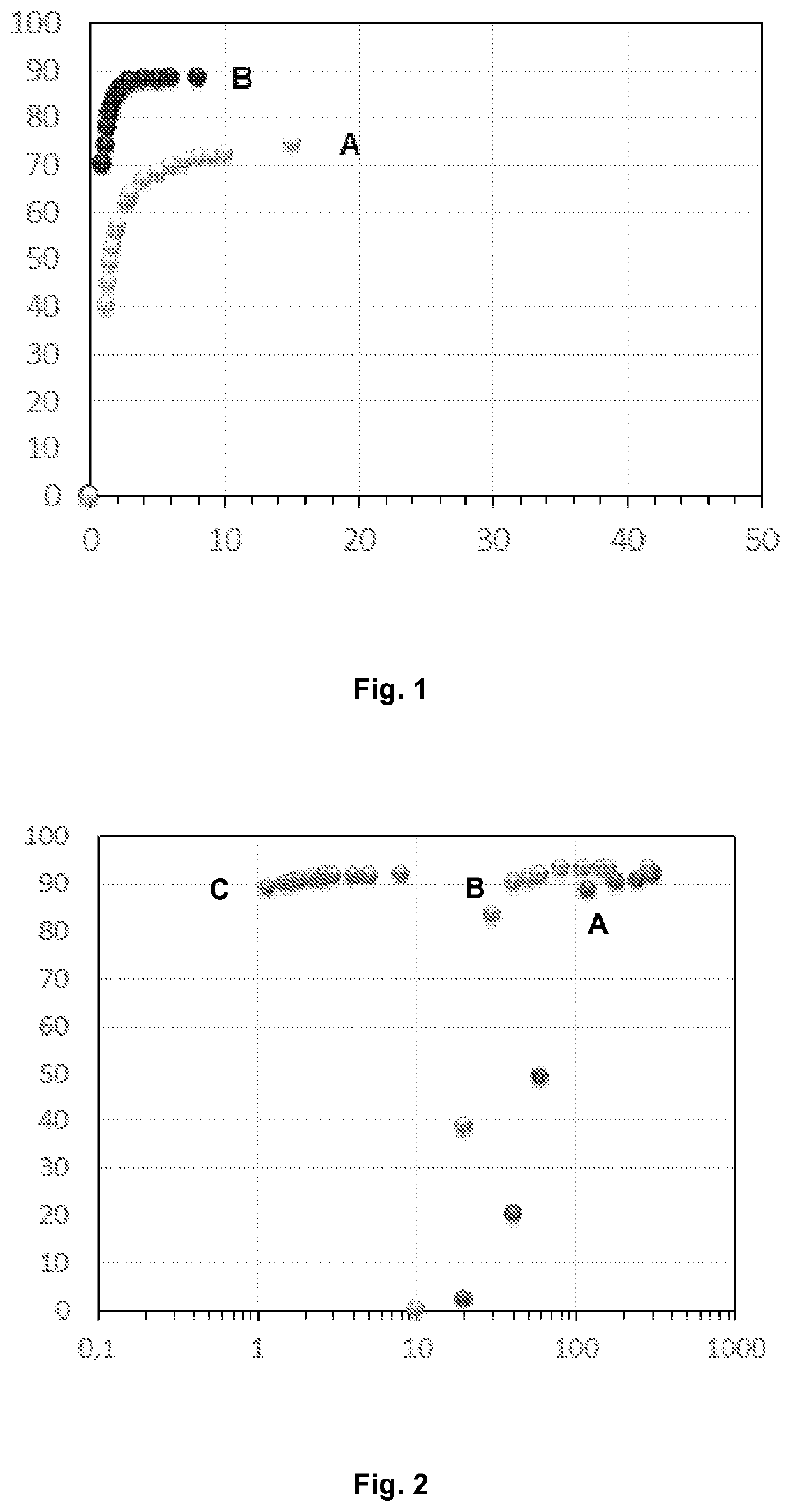
f Viscosity Loss
[0121]A homogenous solution of polymer in brine was prepared. This solution had a salinity of 27 g / L and a polymer concentration of 1000 ppm by weight.
[0122]Firstly, in order to obtain a white reference, this solution was introduced into the measuring chamber of a viscosimeter (Brookfield DVI Prime) at ambient temperature (25° C.) and the viscosity curve was obtained from 5 to 100 rpm (equivalent to a shear rate range from 6 to 122 s−1).
[0123]Then, two different solutions were prepared by adding tetrakis(hydroxymethyl)phosphonium sulfate (THPS) to the solution mentioned above, one containing 200 ppm by weight of THPS (A) and another containing 500 ppm by weight of THPS (B). These solutions were then introduced into the measuring chamber of the viscosimeter (Brookfield DVI Prime) at ambient temperature (25° C.) with a speed of 60 rpm which corresponds to a shear of 73 s−1.
[0124]The measure of time started when THPS was added to the solution and prior to the introducti...
example 2
f Viscosity Loss
[0127]A homogenous solution of polymer in brine was prepared. This solution had a salinity of 27 g / L and a polymer concentration of 1000 ppm by weight.
[0128]Firstly, in order to obtain a white reference, this solution was introduced into the measuring chamber of a viscosimeter (Brookfield DVI Prime) at ambient temperature (25° C.) and the viscosity curve was obtained from 5 to 100 rpm.
[0129]Then, three solutions were prepared, each solution prepared by adding a specific compound into the solution described above. The first solution comprised 10000 ppm by weight of sodium persulfate (A), the second solution comprised 1000 ppm by weight of sodium hypochlorite (B) and the third solution comprised 500 ppm by weight of THPS (C).
[0130]Each solution was then introduced into the measuring chamber of the viscosimeter (Brookfield DVI Prime) at 25° C. for the solution comprising THPS, at 50° C. for the solution comprising sodium hypochlorite and at 65° C. for the solution compr...
example 3
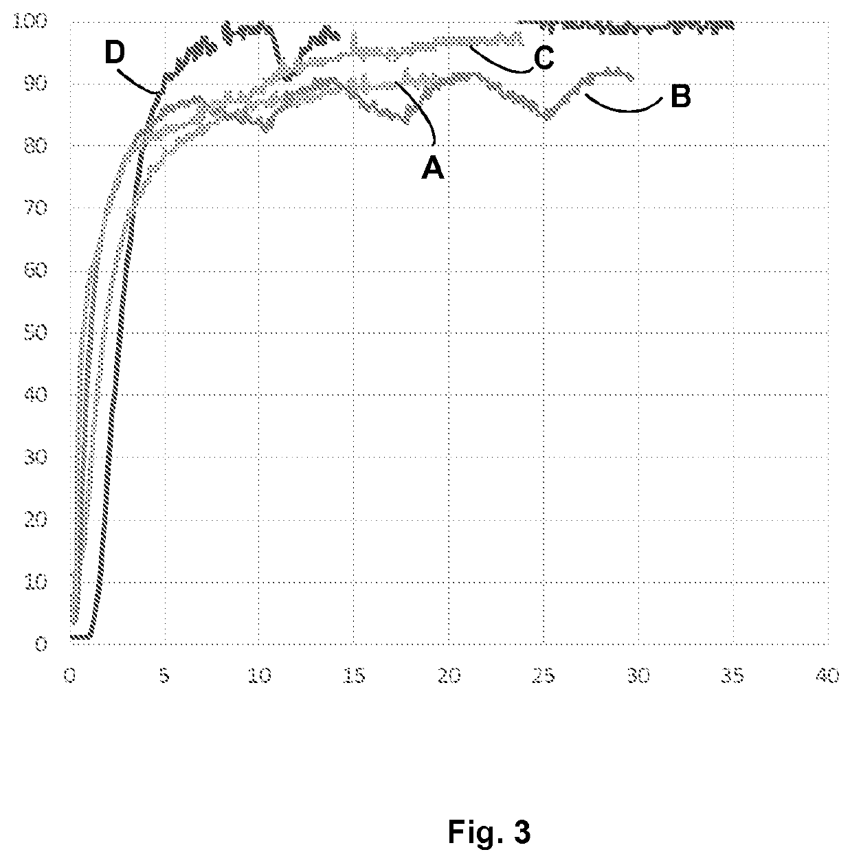
Enhancement
[0134]During this experiment, a syringe pump, a small reactor (300 ml), an oven and a sintered door were used. A ceramic frit was used as porous medium. (permeability of 2 Darcy and 41% porosity) to mimic the injection in a hydrocarbon reservoir.
[0135]10 liters of a brine solution at a salinity of 6 g / L (with 0.2 g / L NaN3) comprising Na2SO4 (0.0075 g), KCl (0.1105 g), CaCl2.2H2O (0.7445 g), MgCl2.6H2O (0.5605 g) and NaCl (4.727 g) were prepared. This brine solution was passed through the porous medium, in order to measure the permeability of the porous medium in the oven at 60° C. (ki=initial permeability). The pressure drop through the frit was measured at constant flow rate. After pressure stabilization, the flow rate was varied and the pressure at stabilization measured. By applying the Darcy law:
DP=Eta(Q) / (kS)L
[0136](with DP=pressure drop, Eta=water viscosity, k=permeability, S=surface area of the porous medium inlet, L=length of the porous medium), the intrinsic p...
PUM
| Property | Measurement | Unit |
|---|---|---|
| temperature | aaaaa | aaaaa |
| concentration | aaaaa | aaaaa |
| salinity | aaaaa | aaaaa |
Abstract
Description
Claims
Application Information