Tool Coating Processing Method

a technology of coating and coating, applied in the field of material processing, can solve the problems of easy blockage of powder feeding pipes, easy peeling of hard phase particles with large particle size in the coating, and complex solid phase reaction

Pending Publication Date: 2022-08-04
DENALI THERAPEUTICS INC +3
View PDF11 Cites 0 Cited by
  • Summary
  • Abstract
  • Description
  • Claims
  • Application Information

AI Technical Summary

Benefits of technology

[0004]In order to overcome the shortcomings of the prior art, an object of the present invention is to provide a tool coating processing method. The processing method solves the feeding problem, the burning problem and the problem of uneven distribution in a coating of hard phase particles in a processing process of a tool coating, improves the hardness, corrosion resistance and wear resistance of the tool coating, and finally improves the service life of the tool.
[0034]Compared with the prior art, one of the above technical solutions provides the following advantages or beneficial effects.
[0035]1. In the present invention, the manner of coaxial powder feeding in combination with side powder feeding can reduce the burning phenomenon of the reinforcing phase due to an excessively high temperature. The present invention avoids a method of mixing the reinforcing phase with the bonding phase by ball milling, because such method destroys the morphology and surface energy of raw materials during ball milling, thereby affecting the cladding process and performance. The reinforcing phase is directly fed into the molten pool using a side powder feeding pipeline instead of a heat source plasma arc, so that the burning loss caused by directly feeding into a heat source can also be reduced.
[0036]2. In the process of preparing a tool coating according to the present invention, the addition of ultrasonic vibration has a significant effect on the flow of metal in the molten pool after cladding, the crystallization nucleation and the growth of grains, and the growing grains are broken under the ultrasonic vibration to form a plurality of nucleation cores, so that the nucleation rate is increased, and a coating with fine grains is finally formed. In addition, the ultrasonic vibration has a good auxiliary effect on the even distribution of hard phase particles in the coating, and an edge of the tool prepared without cracks.

Problems solved by technology

However, a complex solid phase reaction occurs in a ball-milling mixing process of the base powder and hard phase particles.
Therefore, the ball-milling process changes the initial morphology and structural characteristics of original powder materials, and these changes have unpredictable effects on a subsequent coating preparation process.
In addition, when a fine and irregular hard particle powder is separately fed, the problem of blockage of a powder feeding pipe is easily caused.
When a coating is prepared by using hard phase particles with a large particle size for separate powder feeding, there is another problem that the hard phase particles with the large particle size are easily peeled off in the coating.
In the process of laser cladding and plasma cladding, the hard phase particles are usually mixed with the base powder and then fed into a heat source for heating at the same time, so that under the effect of a high-temperature heat source, the hard particles will be partially burnt, waste of the hard phase particles will be caused, and the actual performance of the prepared coating will not be as good as expected.
In addition, the selection of hard phase particles is also a key step in the coating preparation process: during the existing hard phase selection, the issue of density difference between the hard phase particles and the base powder material is not considered, which often results in uneven distribution of the hard phase particles in the coating and cracks in the coating, thereby affecting the usage performance of the coating.
However, according to experimental findings, in one technical solution of the present invention, when tungsten carbide is used as the reinforcing phase, tungsten carbide is deposited on a lower layer of the molten pool, resulting in uneven distribution and poor surface wear resistance of the coating.

Method used


Image

  • Tool Coating Processing Method
  • Tool Coating Processing Method
  • Tool Coating Processing Method

Examples


example 1

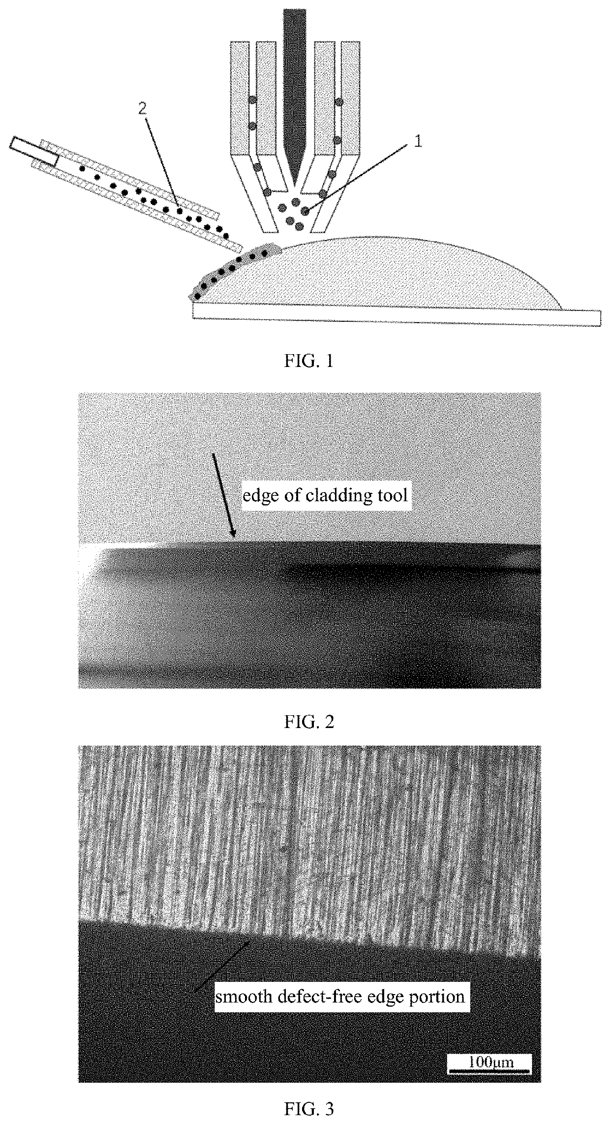
[0077]FIG. 1 shows a schematic diagram of processing, a bonding phase 1 powder is fed from a coaxial powder feeding channel, and a reinforcing phase 2 powder is fed from a side powder feeding channel.

[0078]A tool coating processing method includes:

[0079]Molten pool forming step: a bonding phase is converged to a plasma arc heat source by means of a coaxial powder feeding channel, and the bonding phase is deposited on a tool base material (3Cr13) after melting, so as to form a molten pool. The bonding phase is stainless steel 3Cr13 (with a density of 7.75 g / cm3), and has a powder size of 53-105 μm. A distance between a discharge nozzle of the coaxial powder feeding channel and the tool base material is 8 mm, and a feeding velocity of the bonding phase is 10 g / min.

[0080]Reinforcing phase adding step: a reinforcing phase is fed by means of a side powder feeding channel into the molten pool after a plasma beam is removed. The reinforcing phase is niobium carbide with a density of 7.8 g / ...

example 2

Tool Coating Processing Method

[0087]In contrast to Example 1, a mass ratio of the bonding phase to the reinforcing phase is 3:2.

[0088]The bonding phase has a particle size of 105-180 μm, the reinforcing phase has a particle size of 10-25 μm and a Hall flow velocity of 17 s / 50 g. The remaining processing parameters are the same as in Example 1.

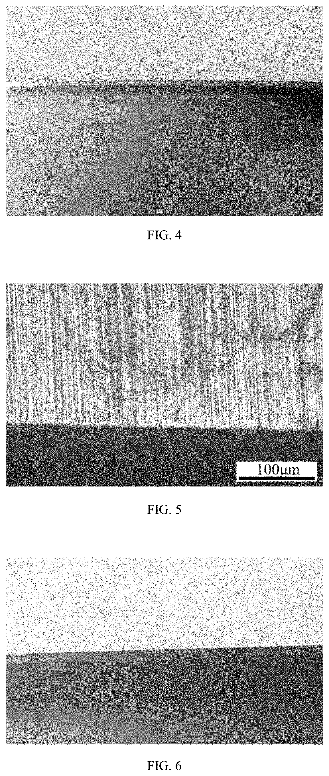
[0089]FIGS. 4-5 show the surface morphology and metallograph of the tool after edge opening are free from corrosion and peeling-off of reinforcing phase particles.

example 3

Tool Coating Processing Method

[0090]In contrast to Example 1, a mass ratio of the bonding phase to the reinforcing phase is 3:7.

[0091]The bonding phase has a particle size of 120-200 μm, the reinforcing phase has a particle size of 15-25 μm and a Hall flow velocity of 16.5 s / 50 g. The remaining processing parameters are the same as in Example 1.

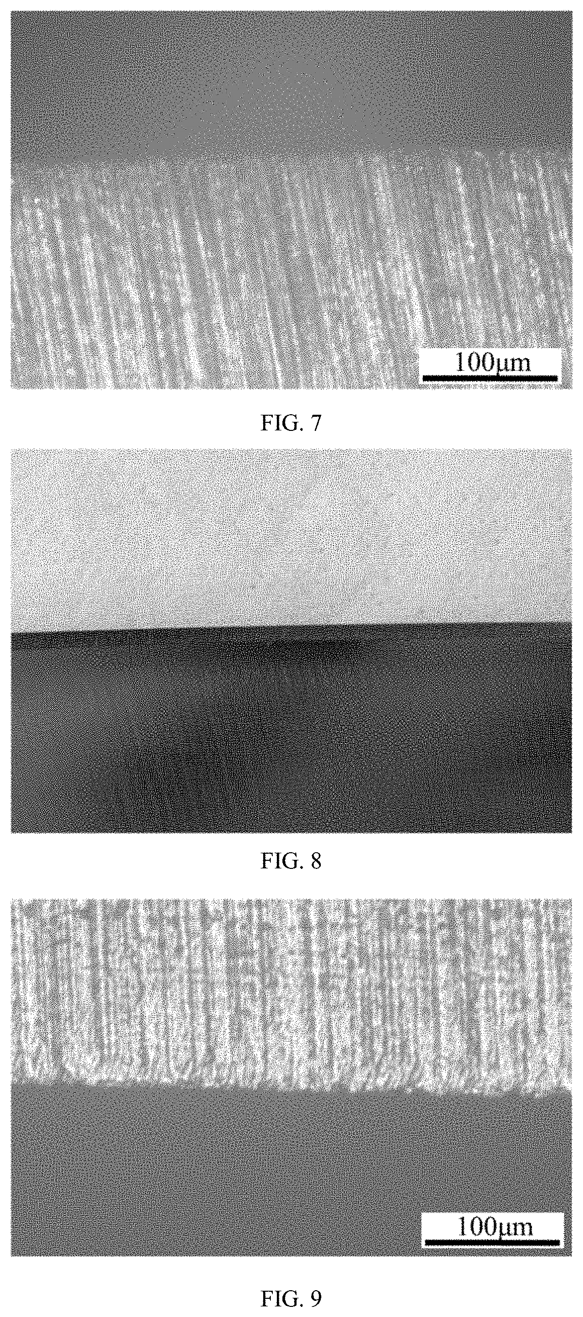
[0092]FIGS. 6-7 show the surface morphology and metallograph of the tool after edge opening are free from corrosion and peeling-off of reinforcing phase particles.


PUM

PropertyMeasurementUnit
sizeaaaaaaaaaa
densityaaaaaaaaaa
particle sizeaaaaaaaaaa

Abstract

A tool coating processing method, comprising a molten pool forming step: converging a bonding phase (1) to a plasma arc heat source by means of a coaxial powder feeding channel, the bonding phase (1) being deposited on a tool base material after melting, so as to form a molten pool; and a reinforcing phase (2) adding step: feeding a reinforcing phase (2) by means of a side powder feeding channel into the molten pool after a plasma beam is removed, cladding the bonding phase (1) and the reinforcing phase (2) under the condition of ultrasonic vibration, and forming a coating on the surface of a tool. The processing method solves the feeding problem, the burning problem and the problem of uneven distribution in a coating of hard phase particles in a processing process of a tool coating, improves the hardness, corrosion resistance and wear resistance of the tool coating, and finally improves the service life of the tool.

Description

TECHNICAL FIELD[0001]The present invention relates to a tool coating processing method, and belongs to the technical field of material processing.BACKGROUND ART[0002]At present, common preparation methods of surface composite coatings are electroplating, surface overlaying, vapor deposition, spray coating, laser cladding and plasma cladding, etc. In order to increase the wear resistance, corrosion resistance, etc. of coatings, carbides or nitrides with high hardness, such as tungsten carbide, titanium carbide and vanadium carbide, are often added in a coating preparation process. A base powder is evenly mixed with a fine hard particle powder by a ball milling process, followed by coating preparation. However, a complex solid phase reaction occurs in a ball-milling mixing process of the base powder and hard phase particles. A mechanical force (shear force, impact force, etc.) generated in the ball-milling process causes a metal powder / hard particles to be subjected to plastic deforma...

Claims


Application Information

Patent Timeline
Patent Type & Authority Applications(United States)
IPC IPC(8): C23C4/08B23K10/02C23C4/134
CPCC23C4/08C23C4/134B23K10/027C23C24/103C23C30/00B23K2103/04C23C24/106
Inventor ZHANG, RUIHUALU, CHAOQU, YUEBO
Owner DENALI THERAPEUTICS INC
Why Eureka
Try Eureka