Hydraulic separator with reduced heat dispersion and control method therefor

a technology of water separator and heat dispersion, which is applied in the direction of space heating and ventilation, lighting and heating apparatus, heating types, etc., can solve the problems of limited thermal efficiency of the system, drawbacks and operating limits, and the quantity of heat or cooling capacity possessed by the inlet fluid is dispersed, so as to reduce the dispersion of energy, and increase the level of thermal efficiency

Pending Publication Date: 2022-08-04
GIACOMINI
View PDF10 Cites 2 Cited by
  • Summary
  • Abstract
  • Description
  • Claims
  • Application Information

AI Technical Summary

Benefits of technology

[0025]More in particular, the object of the present invention is to provide a hydraulic separator with reduced thermal dispersion and a control method, suitable to guarantee an increased level of thermal efficiency with reduced dispersion of energy in the hydronic system.
[0026]A further object of the present invention is to provide to the user an hydraulic separator with reduces heat dispersion and a control method with a limited eddy currents circulation of fluid inside the chamber and with a less mixing of fluids at different temperatures.
[0027]A further object of the present invention is to provide a reduced heat dispersion hydraulic separator capable to assure a high level of strength and reliability over time, such as to be further easily and economically manufactured.

Problems solved by technology

In the operating and functional conditions illustrated in FIGS. 5b and 5b, referring, for example, to a separator installed on a heat production and distribution system for heating, the thermal efficiency of the system is limited because a considerable part of the heat or frigorific capacity of the heat transfer fluid is not used or is dispersed, being diverted together with the compensation fluid flowing inside the hydraulic separator.
The hydraulic separators according to the prior art, even in the ideal condition of FIG. 5c, where the flow rates Q1 and Q2 are substantially equivalent, have however some drawbacks and operating limits.
An important limitation of these traditional hydraulic separators installed on typical hydronic heating and / or cooling systems is due to the fact that, even in the ideal case where the flow rates Q1 and Q2 are equal, the two fluid streams entering and leaving the secondary circuit, and passing through the hydraulic separator, are in fluid contact with each other inside the inner chamber of the separator.
Therefore, a quantity of heat or cooling capacity possessed by the inlet fluid is dissipated by thermal contamination between the two streams through the thermal conduction of the fluid inside the separator chamber.
Another important drawback of the above mentioned hydraulic separators according to the prior art is due to the fact that the heat dispersion through the separator chamber increases together with of the thermal gradient between the cold fluid and the hot fluid, i.e. the “thermal head” of temperature available in the thermodynamic cycle.
A further drawback of traditional hydraulic separators is due to the fact that the thermal contamination between the two fluid streams at different temperatures, at the inlet and outlet port of the hydraulic separator, is even greater in the case of flatwise position installation of the device, position in which the elongated part of the separator body is arranged horizontally; in this case in fact, a less stratification of fluid at different temperatures occurs at the two ends of the hydraulic separator chamber with consequent greater arising of rotary eddy currents and convective flow inside the separator that increase the mixing between fluids at different temperatures, contributing to the increase in heat dispersion.

Method used


Image

  • Hydraulic separator with reduced heat dispersion and control method therefor
  • Hydraulic separator with reduced heat dispersion and control method therefor
  • Hydraulic separator with reduced heat dispersion and control method therefor

Examples


Embodiment Construction

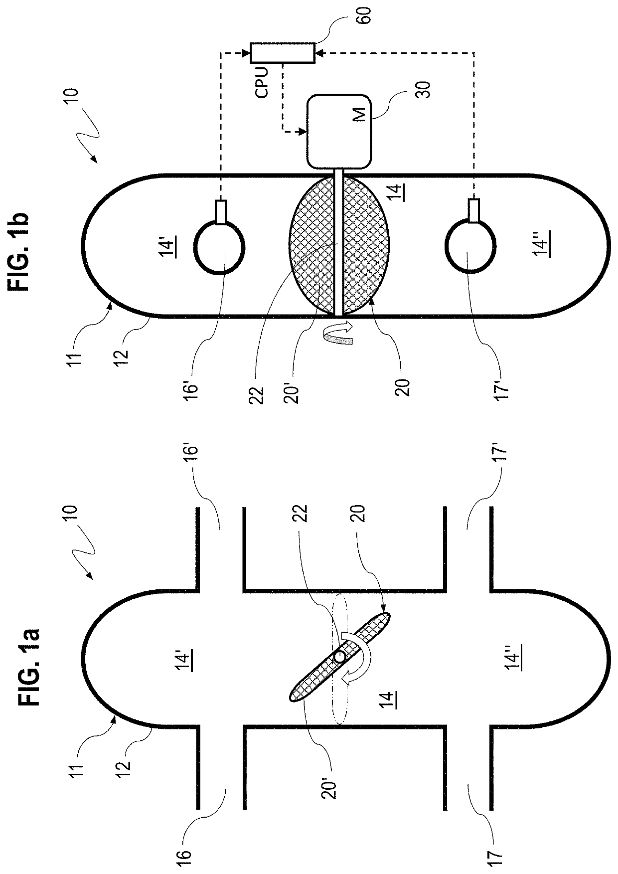
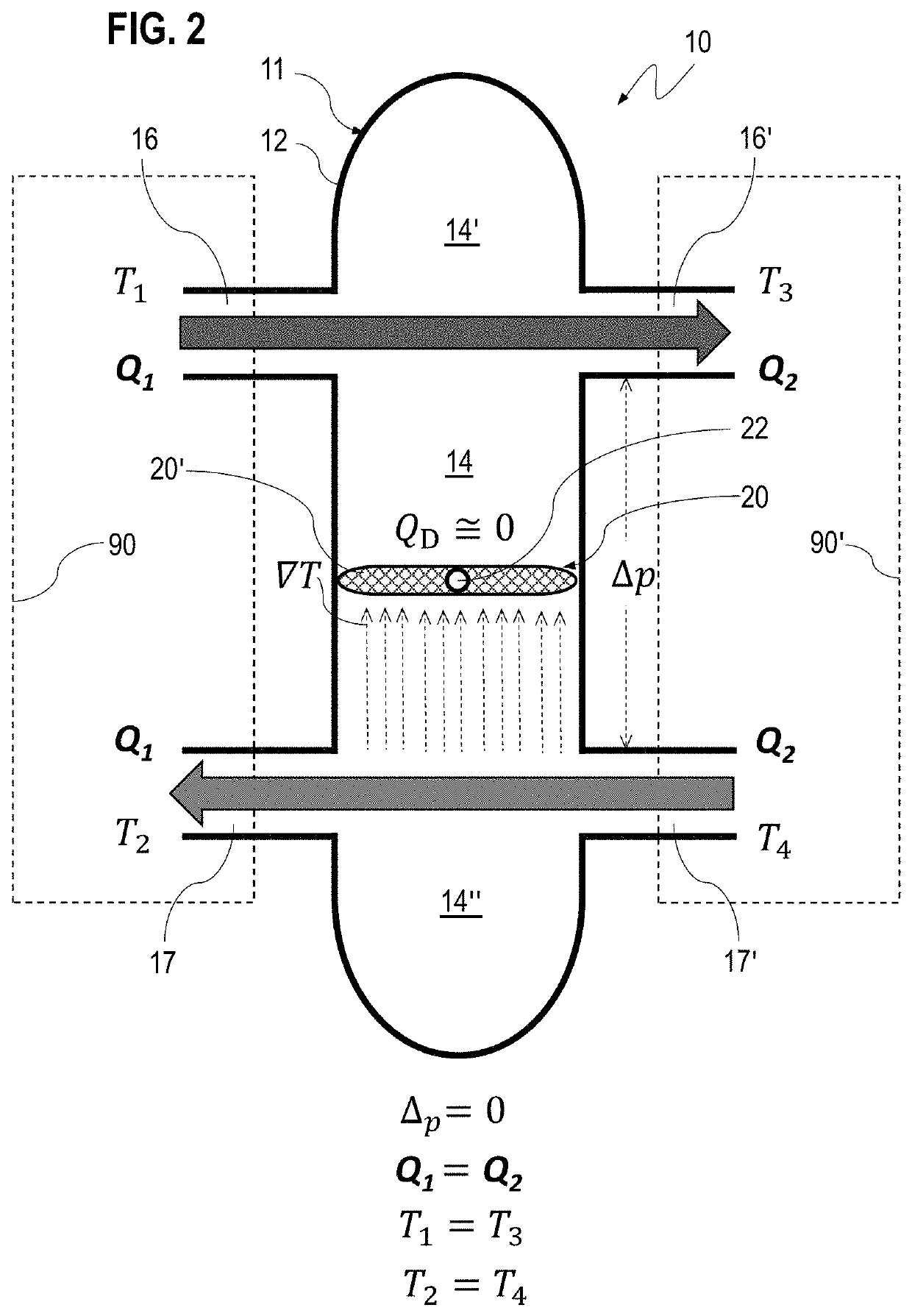
[0046]With initial reference to figures from 1a to 2, it is represented, in a preferred embodiment, a hydraulic separator with reduced heat dispersion, in figures specified with 10, for installation on hydronic systems for heating and / or cooling, said hydraulic separator 10 including:[0047]a hollow body 11 with a casing 12 internally defining a chamber 14;[0048]at least two first through openings 16, 16′, for the delivery of a fluid and at least two second through openings 17, 17′, for the return of a fluid, said first openings 16, 16′ and said second openings 17′, 17 being obtained on said casing 12 of the body 11 and being suitable to put in fluid communication said chamber 14 to external circuits by hydraulic connection means.

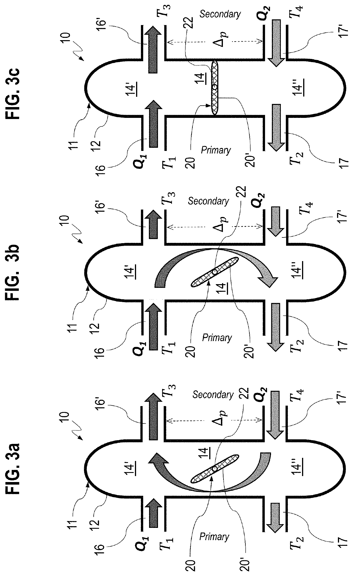
[0049]The hydraulic separator 10 of the present invention has the innovative feature of comprising at least one mobile element 20 suitable for separating the chamber 14 of the body 11 in a first portion 14″ of volume and a second portion 14″ of volume, in su...


PUM


Abstract

A hydraulic separator for hydronic systems for heating and / or cooling, including a hollow body with a casing, internally defining a chamber; at least two first through openings for the delivery of a fluid, and at least two second through openings for the return of the fluid, said first openings and said second openings being made on said casing of the body and being suitable to put in fluid communication said chamber to external circuits by hydraulic connecting means, further includes at least a mobile element suitable for separating said chamber of the body in a first portion and a second portion, in such a way to reduce the opening section of passage and of fluid contact between said first portion and said second portion. The invention further includes a control method for the hydraulic separator and hydronic systems for heating and / or coding.

Description

FIELD OF TECHNOLOGY[0001]The present invention refers to a hydraulic separator with reduced heat dispersion and a control method thereof.[0002]More specifically, the present invention refers to a hydraulic separator device for hydronic and thermic systems with a reduced heat dispersion between the fluid flows in contact with each other at different temperatures, at the inlet and outlet of the separator, and to the relative control method thereof.BACKGROUND[0003]In up-to-date hydronic and thermal systems for heating and / or cooling, hydraulic devices so-called separators are widely used and they are designed to decouple an hydraulic circuit in a upstream hydraulic circuit and a downstream hydraulic circuit, in order to make them independent as flow rates, dynamic pressures and other plant fluid-mechanic disturbance factors such as fluid circuit dependencies, eddy currents, etc.[0004]The hydraulic separator is typically arranged between the manifold of the “primary” upstream circuit, t...

Claims


Application Information

Patent Timeline
Patent Type & Authority Applications(United States)
IPC IPC(8): F24D19/10F24D3/10
CPCF24D19/1015F24D3/1091F24D2220/0271F24D2220/042F24D3/1066F24D2220/0221
Inventor MOLINA, SAMUELEROSA BRUSIN, MARCOARRUS, PAOLO
Owner GIACOMINI
Why Eureka
Try Eureka