
System for Offshore Power Generation

a power generation system and system technology, applied in the direction of machines/engines, mechanical equipment, transportation and packaging, etc., can solve the problems of unfavorable inclination force, unfavorable inclination force, and high turbulence in air flow

Pending Publication Date: 2022-08-25
RAMDE ROAR
View PDF3 Cites 0 Cited by
  • Summary
  • Abstract
  • Description
  • Claims
  • Application Information

AI Technical Summary

Benefits of technology

The patent describes a wind turbine installation on a buoyancy body, such as a ship's hull. The buoyancy body is designed to be stable and able to withstand extreme weather conditions. The wind turbine can be protected by active and passive dampening devices placed in a well within the buoyancy body. The dampening devices help reduce and control the pitching / heave angle of the buoyancy body, which can impact the power production of the wind turbine. The buoyancy body can also act as a sensor to measure the pitching / heave angle of incoming waves, which can be used to predict the occurrence of waves and activate the maneuvering unit to prepare for them. As a result, the wind turbine can continue producing energy even in rough sea conditions.

Problems solved by technology

Such fixed anchoring does not allow the buoyancy body, and thus the wind turbine, to rotate into the wind direction, whereupon the wind turbine itself must be equipped with rotating devices on top of the mast to control the wind turbine so that it turns up into the wind as the wind changes direction.
This results in unnecessary strength and stability forces, or drag forces on the unit, which creates high turbulence in the air flow at the rear of where the wind hits the mast.
Units with small contact surfaces to the sea surface will have a large weight load per unit area of the contact surface and therefore be sensitive to weight changes and lack the ability to withstand inclining forces from in strong wind or other external impacts.
The load capacity is therefore limited and complicated by the need of fixed ballast to achieve the necessary righting moment.
Transport of floating wind-power stations can provide major challenges.
Or, a relocation to other positions can only be done by extensive operations and is very sensitive to weather.
Such arrangements tend to have major environmental impact and will, for example, be a threat to bird populations, interference in the seabed by buried anchoring systems and power and signal cables will further have an impact on marine life and thus also the fishing industry.
The required area will also be a hindrance for example the shipping traffic.

Method used


Image

  • System for Offshore Power Generation
  • System for Offshore Power Generation
  • System for Offshore Power Generation

Examples


Embodiment Construction

[0082]The following description of the exemplary embodiments of the present invention refers to the accompanying drawings. The same reference numbers in different drawings identify the same or similar elements. The following detailed description does not limit the invention or the scope of protection, as the scope of protection is defined by the person skilled in the art's interpretation of the scope of the appended claims.

[0083]Reference throughout the specification to “one embodiment” or “an embodiment” means that a particular feature, structure or characteristic described in connection with an embodiment is included in at least one embodiment of the subject matter disclosed. Thus, the appearance of the phrases “in one embodiment” or “in an embodiment” in various places throughout the specification is not necessarily referring to the same embodiment.

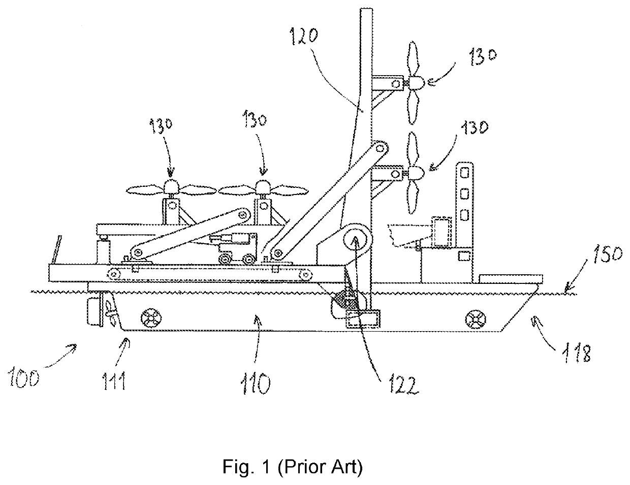
[0084]FIG. 1 shows prior art of wind turbines arranged on a frame on a ship, as mentioned in US 2007138021, showing several wind turb...


PUM


Abstract

An offshore power generating system has a buoyancy body shaped as a hull with a bow and aft end, and elongated mast extending up from the buoyancy body to the buoyancy body about a horizontal transverse axis. A rotor is supported in one end of the longitudinal mast for rotation about a horizontal axis. The buoyancy body is kept in position with the bow turning up into wind and incoming waves. Rotational support of the mast has a horizontal rotational axis through the center of gravity of the mast that lies in the center plane of the buoyancy body above the aft end when the buoyancy body lies in operational position in calm sea with the rotational axis of the rotational support of the mast orthogonal to the center plane of the buoyancy body. A method for on-board loading and commissioning of mast with installed rotor on-board a buoyancy body.

Description

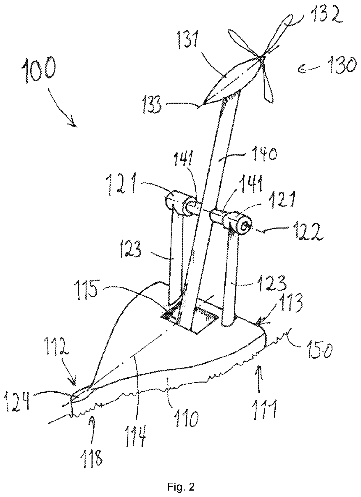
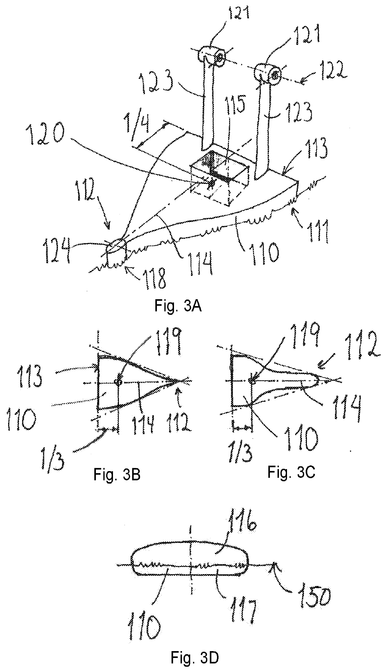
BACKGROUND[0001]The disclosed embodiments relate to a system for offshore power generation utilizing wind for generating power. The system comprises a mast with a wind turbine in a hinged installation on a floating buoyancy body.[0002]More specifically the disclosure relates to an offshore power generating system comprising:[0003]a buoyancy body being a hull with a bow and an aft end;[0004]an elongated, aerodynamic designed mast projecting upwards from the buoyancy body, rotatably supported on the buoyancy body about a horizontal transverse axis;[0005]a rotor supported in one end of the elongated mast for rotation about a horizontal axis oriented in the longitudinal direction of the buoyancy body;[0006]an arrangement for keeping the buoyancy body in a position with the bow turning up into the wind and incoming waves.[0007]Also disclosed is a method for on board loading and preparing the mast with installed rotor into operation on a buoyancy body.[0008]It is known from floating wind ...

Claims


Application Information

Patent Timeline
IPC IPC(8): F03D13/25F03D80/50
CPCF03D13/25F03D80/50F03D7/042B63B2035/446B63B43/02F05B2240/95F05B2240/93Y02E10/72Y02E10/727E02B2017/0091
Inventor RAMDE, ROAR
Owner RAMDE ROAR
Learn More