Brushless direct drive linear servo actuator

a servo actuator and direct drive technology, applied in the direction of dynamo-electric machines, magnetic circuit shapes/forms/construction, structural associations, etc., can solve the problems of difficult to ensure accuracy, low accuracy, and sensitive manufacturing cost in the large-scale manufacturing application field, so as to improve reliability and service life, and ensure the high accuracy of long-term operation of the actuator. , the effect of improving the heat dissipation performan

Pending Publication Date: 2022-11-17
SUZHOU FUGENA ELECTROMECHANICAL CO LTD
View PDF4 Cites 0 Cited by
  • Summary
  • Abstract
  • Description
  • Claims
  • Application Information

AI Technical Summary

Benefits of technology

[0023]The present invention has the following advantageous effects: the stator of the actuator includes a pair of armatures arranged in mirror symmetry relative to the mover, the force applied to the mover at the direction perpendicular to the central plane of mirror symmetry is balanced, and the mover bears only pushing and pulling forces in a moving direction of the mover. Also, different from the typical mechanically assembled structure of armature, mover and housing, where clearances accumulate and add up and thus result in an increased air gap variation between the mover and the stator, the armatures of the stator of the present invention are integrally encapsulated by the housing, and thus the cavity for the mover is formed and positioned relative to the stator poles by a mould, with very high position accuracy; therefore, the mover has very little friction within the housing, which greatly reduces sliding abrasion, thereby improving the expected service life and reliability of a sliding system and meanwhile increasing the effective output of the system. When bushings are arranged between the frame of the mover and the corresponding surface of the inner wall of the housing, and between the output end of the mover and the corresponding surface of the housing, and the bushings are made of a wear-resistant and load-resistant material, the load-resistant capacity of the system can be further improved and frictions are reduced.
[0024]The stator of the actuator is integrally encapsulated by the housing, and the heat generated by the wire coils of the armatures of the stator can be conducted through the completely covering and integrally encapsulating housing, which significantly enhances the heat dissipating performance, and improves reliability and service life.
[0025]Both the emitter and the receiver are arranged on the central plane of mirror symmetry of the stator, and the magnetic field generated here by the armatures of the stator and the magnet of the mover has a magnetic-field component of nearly zero along the central plane of mirror symmetry and perpendicular to the moving direction. When the position signal receiver detects along said magnetic-field component, it is completely free of interferences of the magnetic field of the actuator. Meanwhile, the mover performs a direct drive motion without any mechanical conversion clearances at all, which means that there is no deviation caused by mechanical conversion, thereby enabling a step-less position control at any position. A high accuracy of long-term operation of the actuator is thus guaranteed.
[0026]The stator of the actuator is integrally encapsulated by the housing, allowing components to be formed in high accuracy, resulting in a concise and compact structure with a reduced total number of components. The actuator can be manufactured and assembled in a simple and reliable manner. In a limited stroke range, there is no need of a complicated electronic controller. The actuator can be controlled in the same manner as a common brushed actuator. Therefore, the total production and usage cost are very low. The present invention is especially suitable for large-scale manufacturing application filed.

Problems solved by technology

Meanwhile, such a large-scale manufacturing application field is very sensitive to manufacturing cost.
However, for the demanding application environment of exhaust gas recirculation valve, the above technical solution has several insufficiencies.
Considering the temperature variations during usage, necessary clearance must be designed appropriately between mating components to avoid getting stuck; due to mechanical conversion mechanism amplification, a tiny clearance will be amplified as a position deviation at the output end; after long-time, frequent operations, movable components will be deteriorated and thus the accuracy is lower.
Also, the position signal sensor needs to be separately arranged at the output end, where given the surrounding electromagnetic interferences, the structure arrangement is a challenge and it is difficult to ensure the accuracy.
Mechanical components are also subjected to high temperatures, load impacts, etc., and thus they are usually the source of failure and greatly reduce the service life and reliability of the system.
In consideration of the cost, such types of solutions usually adopt brush motors in which the brush abrasion limits the system service life, and thus such solutions can hardly meet the application requirements of high-level reliability internal combustion engines.
Although the limitation of brush abrasion is eliminated, the electronic controller cost greatly increases for commutation and actuator control.
As for high-temperature application environment like an internal combustion engine, the reliability of electronic components greatly reduces with the increase of temperature; once its temperature grade reaches over 125° C., the cost will significantly increase.
In order to ensure the displacement accuracy, an additional position signal sensor is usually arranged at the output end, which increases not only the difficulty of electronic component arrangement, but also the cost.
Moreover, this solution still cannot avoid the above-mentioned insufficiencies of mechanical motion conversion mechanism.
The related problems of accuracy and reliability of the mechanical mechanism still exist.
Therefore, it is still not the ideal solution.
Although various professionals have explored in the field of brushless direct drive linear actuator, no solution has been published for the above-mentioned harsh application field.
Such solutions, however, have low power efficiency and low value for industrial application.
However, such structure is complicated, with big size and also high manufacturing cost; it cannot meet the requirements of reliability and long service life for harsh application environments; and it cannot realize position feedback control.
Therefore, it cannot meet the above application requirements of high reliability, high accuracy, and low cost.

Method used


Image

  • Brushless direct drive linear servo actuator
  • Brushless direct drive linear servo actuator
  • Brushless direct drive linear servo actuator

Examples


first embodiment

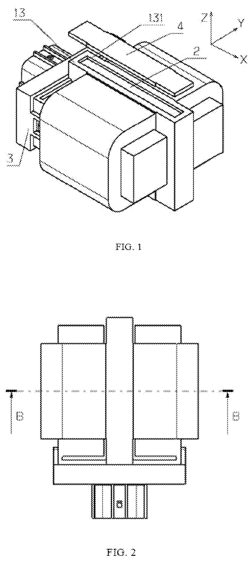
[0038]FIG. 1 shows an isometric view of a brushless direct drive linear servo actuator according to the present invention. The specific implementation is as follows: the actuator comprises a stator 1 (not shown), a mover 2, a cover 3, a cap 4, and a housing 13. The stator 1 comprises a pair of armatures and is integrally encapsulated by the housing 13, wherein the housing 13 may be made of plastic or other materials capable of encapsulating and then solidifying, and wherein a cavity 131 for the mover is formed inside the housing 13, the mover 2 is mounted into the cavity 131 for mounting the mover through a mounting opening of the housing 13, and the cavity 131 for the mover is closed by a cap 4. The cavity 131 for the mover retains the mover 2 therein, and ensures that the mover 2 reciprocates along a direction of Z axis within the cavity 131 for the mover. The cover 3 is disposed on one side of the housing 13.

[0039]FIG. 2 shows a top view of the brushless direct drive linear servo...

second embodiment

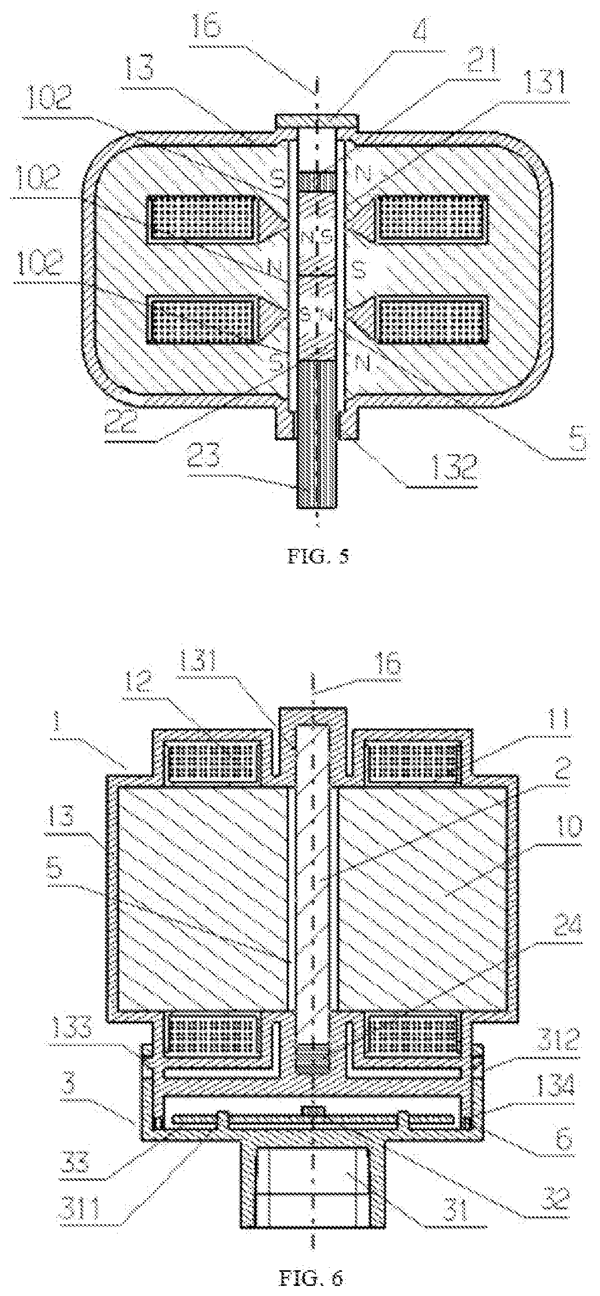
[0049]The skilled in the art may understand that, a structure of the bushing in the second embodiment may also be replaced with a sliding shaft. Specifically, at least one sliding shaft extends into the cavity 131 for mounting the mover, and the mover frame 21 is provided with shaft holes or grooves in the number and position corresponding to the sliding shafts, wherein the shaft holes or grooves are in sliding fit with the respective sliding shafts to guide the mover in the cavity 131 for mounting the mover. Further, the at least one sliding shaft includes a plurality of sliding shafts, more preferably two sliding shafts. Further, the sliding shaft is fixed to the housing 13. Further, under the configuration where two sliding shafts are provided, one shaft hole or groove, at a side of the mover frame 21, for example, a side close to the emitter 24, is a circular through-hole, which is in precise but loose fit with the respective sliding shaft, while the other shaft hole or groove i...


PUM


Abstract

The present disclosure provides a brushless direct drive linear servo actuator, comprising: a stator, a mover and a housing, wherein the stator is a pair of armatures arranged in mirror symmetry at both sides of the mover, the housing integrally encapsulates the stator and forms a cavity for the mover at the mover, and the mover has an output end protruding out of the housing and is linearly movable along a direction of the output end. A displacement signal emitter is provided at a side of the mover, and a signal receiver is provided within a cover arranged outside the housing on said side for detecting a displacement signal emitted by the emitter of the mover. The actuator of the present disclosure is characterized by high reliability, high accuracy and low cost.

Description

FIELD OF THE INVENTION[0001]The present invention relates to a brushless direct drive linear servo actuator, which belongs to the field of brushless motor, in particular relates to a brushless direct drive linear servo actuator with moving magnet and integral position feedback, of which an armature-composed stator is integrally encapsulated.BACKGROUND OF THE INVENTION[0002]In the field of intake and exhaust applications of internal combustion engines, the continuous upgrade of emission regulations requires more precise, faster, and more reliable control of fuel consumption and exhaust emission. For example, exhaust gas recirculation valves, electrically regulated turbo-charging technology, etc. are used for these purposes. However, these functions require the use of actuators which are resistant to high temperatures, vibrations and corrosions, and also accurate, robust and reliable for long service life. Meanwhile, such a large-scale manufacturing application field is very sensitive...

Claims


Application Information

Patent Timeline
Patent Type & Authority Applications(United States)
IPC IPC(8): H02K41/03H02K11/21
CPCH02K41/031H02K11/21H02K41/02H02K16/00H02K29/06H02K1/12H02K9/22H02K5/04H02K11/215H02K33/16
Inventor ZHANG, HAIFENGYING, CHENGJIONG
Owner SUZHOU FUGENA ELECTROMECHANICAL CO LTD
Why Eureka
Try Eureka