Iron-based permanent magnets and their fabrication as well as iron-based permanent magnet alloy powders for permanent bonded magnets and iron-based bonded magnets

a technology of permanent magnets and alloy powders, which is applied in the direction of magnetic materials, nanomagnetism, and magnetic bodies, can solve the problems of lowering mechanical strength, limiting the use of permanent magnets in power motors and actuators in home electronic goods and general electric goods, and ease of defect formation

Inactive Publication Date: 2000-02-01
SUMITOMO SPECIAL METAL CO LTD
View PDF4 Cites 24 Cited by
  • Summary
  • Abstract
  • Description
  • Claims
  • Application Information

AI Technical Summary

Problems solved by technology

Permanent magnets used in stepping motors, power motors and actuators utilized in home electronic goods and electric goods in general are mainly limited to hard ferrites, which have various problems such as, demagnetization at low temperatures with the fall of iHc, the ease of formation of defects, cracks and a lowering of mechanical strength due to the quality of the a ceramic material, and the difficulty to fabricate complicated forms.
Further, with the miniaturization of magnets used in magnetic rolls and speakers, an increase in Br is being sought as present hard ferrite magnets cannot give more than 5 kG Br.
Production of Nd requires many metal separation and reduction processes which in turn needs large scale equipment.
As well as this, for 90% magnetization, a magnetic field of close to 20 kOe is required and there are problems with the magnetization characteristics such as being unable to achieve complicated multipole magnetization such that the pitch between the magnetic poles is less than 1.6 mm.
However, it is insufficient as a rare earth magnetic material with a low iHc in the range 2 kOe.about.3 kOe, and is unsuitable for industrial use.
One such example is to add rare earth elements other than Nd, such as Dy and Tb, which should improve iHc but, apart from the problem of rising material costs from the addition of expensive elements, there is also the problem that the magnetic moment of the added rare earth elements combines antiparallel to the magnetic moment of Nd or Fe, leading to a degradation of the magnetic field and the squareness of the demagnetization curve (R. Coehoorn, J. Magn. Magn. Mat., 83 (1990) 228.about.230).
In each case, for Nd--Fe--B-type magnets whose main phase is an Fe.sub.3 B-type compound, it is possible to create hard magnetic materials with a heat treatment after amorphizing by quenching, but their iHc is low and the cost performance of using them instead of hard ferrite magnets is unfavourable.
This incapability of providing a high-enough iHc is caused by a large grain size of the soft magnetic phase, typ...

Method used


Image

  • Iron-based permanent magnets and their fabrication as well as iron-based permanent magnet alloy powders for permanent bonded magnets and iron-based bonded magnets

Examples


example 1

To produce compositions No. 1.about.18 shown in Table 1, a total of 30 gr was weighed out using more than 99.5% pure Fe,Co,Cr,B,Nd,Pr,Al,Si,S,Ni,Cu,Zn,Ga,Ag,Pt,Au or Pb metal, placed in a quartz crucible having a 0.8 mm diameter orifice in its base, and melted by high frequency heating under an Ar atmosphere at a pressure of 56 cmHg. After reaching a melting temperature of 1400.degree. C., the molten surface was pressurized by Ar gas, and the molten alloy was injected from a height of 0.7 mm from the outer surface of a Cu roll rotating at a circumferencial velocity of 20 m / sec at room temperature, forming an melt quenched thin film 2 mm.about.4 mm wide and 20 .mu.m.about.40 .mu.m thick.

The obtained thin film was shown to be amorphous using characteristic Cu K.alpha. x-rays.

The temperature of this thin film was then raised to above 580.degree. C..about.600.degree. C., at which crystallization begins, under an Ar atmosphere at the rate shown in Table 1, and then maintained for seven h...

actual example 2

On measuring the Curie temperature with a thermomagnetic balance of sample No 3, which has the magnetic characteristics listed in Table 2, we found the presence of a main ferromagnetic phase having a Curie temperature of 849.degree. C. and another ferromagnetic phase having a Curie temperature of 388.degree. C. After comparing x-ray analyses, the former is thought to be .alpha.-Fe in a solid solution with Co, and the latter a Nd.sub.2 Fe.sub.14 B-type compound (with Fe partially replaced by Co).

actual example 3

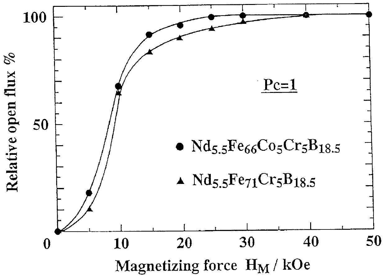
After processing bonded magnet No. 3, which has the magnetic characteristics listed in Table 3, so that the permeance coefficient becomes 1, the magnetization curve, shown in FIG. 1, has been found by pulse magnetizing from a weak magnetic field in the range 2 kOe.about.50 kOe and each time measuring the residual magnetic flux density of the magnet in the open magnetic configuration. By taking the magnetization rate for the residual magnetic flux density at 50 kOe as 100%, the curve is found by estimating the magnetization rate for each magnetization field as a relative ratio of the residual magnetic flux density. The magnetic field required for 90% magnetization is about 13 kOe.


PUM

PropertyMeasurementUnit
Nanoscale particle sizeaaaaaaaaaa
Temperatureaaaaaaaaaa

Abstract

With the intention of establishing fabrication methods for cheaply produced (Fe,Co)-Cr-B-R-type bonded magnets or (Fe,Co)-Cr-B-R-M-type bonded magnets containing few rare earth elements and having a coercive force iHc above 5 kOe and a residual magnetic flux density Br above 5.5 kG matching the cost performance of hard ferrite magnets, we have obtained iron-based permanent magnets consisting of microcrystal clusters where the average crystal size of each component phase is in the range 1 nm DIFFERENCE 30 nm and where both a soft magnetic phase consisting of a ferromagnetic alloy whose main components are alpha -Fe and a ferromagnetic alloy having iron, and a hard magnetic phase having a Nd2Fe14B-type crystal structure coexist within the same powder particles, by melt-quenching of a (Fe,Co)-Cr-B-R(Pr,Nd)-type molten alloy or a (Fe,Co)-Cr-B-R-M (M=Al,Si,S,Ni, Cu,Zn,Ga,Ag,Pt,Au,Pb)-type molten alloy of a particular composition containing few rare earth elements, to obtain an essentially amorphous structure or a structure both amorphous and with small amounts of fine crystals, and by applying a crystallization heat treatment under specific conditions. By grinding this iron-based permanent magnet to an average powder particle size of 3 mu m DIFFERENCE 500 mu m and combining the resultant iron-based permanent magnet alloy powder with a resin, we can obtain an iron-based bonded magnet with good thermal and magnetic properties and with the magnetic characteristics iHc>/=5 kOe, Br>/=5.5 kG and (BH)max>/=6 MGOe.

Description

1. Field of the inventionThis invention, relating to iron-based permanent magnets and alloy powders for iron-based bonded magnets and their fabrication, used for obtaining suitable iron-based bonded magnets for all kinds of motors, actuators and magnetic circuits for magnetic sensors, as well as magnetic rolls and speakers, regards iron-based permanent magnets and their fabrication which yield isotropic iron-based bonded magnets having a residual magnetic flux density Br greater than 5 kG unobtainable from hard ferrite magnets. These are produced by quenching an (Fe,Co)--Cr--B--R molten alloy or a (Fe,Co)--Cr--B--R--M (M=Al,Si,S,Ni,Cu,Zn,Ga,Ag,Pt,Au,Pb) molten alloy, with small amounts of rare earth elements added, using either, a melt-quenching process utilizing a rotating roll, splat quenching, a gas atomizing method, or a combination of these methods, to obtain an essentially amorphous structure or a structure containing small amounts of microcrystals dispersed within an amorphou...

Claims


Application Information

Patent Timeline
IPC IPC(8): H01F1/057H01F1/032B22F9/00
CPCB22F9/008B82Y25/00H01F1/0576H01F1/0577H01F1/0578H01F1/0579
Inventor KANEKIYO, HIROKAZUHIROSAWA, SATOSHI
Owner SUMITOMO SPECIAL METAL CO LTD
Why Eureka
Try Eureka