Low absorption coatings for infrared laser optical elements

a technology of laser optical elements and coatings, applied in the field of low absorption thin film coatings, can solve the problems of significant optical energy being absorbed in the coating, focal point shifting away from the intended position, heat generation, etc., and achieve the effect of effective and practical low absorption

Inactive Publication Date: 2000-02-01
II VI
View PDF2 Cites 33 Cited by
  • Summary
  • Abstract
  • Description
  • Claims
  • Application Information

AI Technical Summary

Benefits of technology

BaF.sub.2 has not been used effectively as a CO.sub.2 optic thin film coating material, and it would be an advantage to provide an effective and practical low absorption BaF.sub.2 -based thin film AR coating and other coatings such as partial reflector coatings for output couplers, beamsplitters, total reflectors, and various other types of coatings used in high power CO.sub.2 lasers.

Problems solved by technology

AR coatings must be carefully designed and manufactured, otherwise significant optical energy will be absorbed in the coating, which unfortunately generates heat.
One significant heat-related problem is the "thermal lens effect" caused by the temperature dependency of the refractive index, the thermal expansion of the optic and to a lesser extent the temperature induced stress dependency of the refractive index.
The thermal lens effect can significantly shift the focal length and thereby cause the focal point to shift away from its intended position, a highly undesirable result for many applications such as precision laser-cutting of metal.
Moreover, the thermal lens can also introduce aberrations which distort the laser beam and increase the size of the focused spot, which can degrade cutting speed and quality.
Unfortunately, thorium (Th) is radioactive, and therefore an intensive worldwide search for a suitable replacement has been ongoing for many years, as evidenced by many publications such as Rahe et al., Absorption Calorimetry and Laser Induced Damage Threshold Measurements of AR-coated ZnSe and Metal Mirrors at 10.6 .mu.m., Symposium on Laser-Induced Damage in Optical Materials, SPIE Vol. 1441, p.
Only two fluorides are known to yield absorption levels lower than ThF.sub.4, these being PbF.sub.2 and BaF.sub.2. PbF.sub.2 can provide a good single-layer low reflection AR coating due to its higher index, but a second high index layer does not improve the low reflectance of the coating significantly.
Another disadvantage of PbF.sub.2 -based coating is that it is difficult to manufacture and process and furthermore, its initial absorption values are believed to be higher than those of a BaF.sub.2 -based AR coating.
However, the low absorption value of the BaF.sub.2 -based coating quickly increased so that in less than 20 days its absorption exceeded that of the ThF.sub.4 -based AR coating, and then continued to increase at a much faster rate.
However, as Rahe described, conventional BaF.sub.2 -based coatings exhibit poor "ageing" performance; i.e. in a matter of days the absorption quickly rises to meet, and then exceed that of conventional ThF.sub.4 -based coatings.
The article concluded that such fluorides would not be good substitutes for ThF.sub.4 in most infrared applications, especially those at 10.6 microns.
Also, the lower temperature reduces localized thermal expansion of the optic's surfaces, which could otherwise significantly distort a CO.sub.2 laser beam.

Method used


Image

  • Low absorption coatings for infrared laser optical elements
  • Low absorption coatings for infrared laser optical elements
  • Low absorption coatings for infrared laser optical elements

Examples


first embodiment

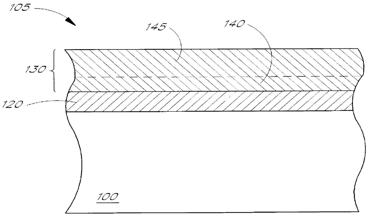
The interior layer (BaF.sub.2) has an optical thickness between about 0.12 .lambda. (9000 .ANG.) and 0.21 .lambda. (15700 .ANG.), and the exterior layer (ZnSe) has a corresponding optical thickness between about 0.56 .lambda. (24600 .ANG.) and 0.52 .lambda. (22850 .ANG.). That is, in a first embodiment according to this example the respective thicknesses are 0.12 .lambda. (9000 .ANG.) and 0.56 .lambda. (24600 .ANG.), and in a second embodiment according to this example the respective thicknesses are 0.21 .lambda. (15700 .ANG.) and 0.52 .lambda. (22850 .ANG.).

second example

Still using the first solution set, m.sub.1 and m.sub.2 can be varied to provide many possible designs. In the following example, we start again where T.sub.1 =0.153 .lambda. (11,450 .ANG.) and T.sub.2 =0.043 .lambda. (1900 .ANG.) for zero theoretical reflectance of a low absorption AR BaF.sub.2 / ZnSe coating at 10.6 microns. By choosing m.sub.1 =0 for the interior layer and m.sub.2 =2 for the exterior layer, the interior layer remains thin while the exterior layer is increased by two absentee layers, giving a resulting thickness of t.sub.2 =0.043 .lambda.+(2.multidot.0.5 .lambda.)=1.043 .lambda. (45900 .ANG.) for the optimum solution of the exterior layer.

As in the first example, a range of thicknesses around the optimum T.sub.1 and T.sub.2 can also provide an acceptable AR coating, even though the reflectivity may be slightly greater. Following is an example of a range of values that will provide a reflectivity of approximately 0.5% or less for an AR BaF.sub.2 / ZnSe coating design...

third example

Still using the first solution set, in the following example we start again where T.sub.1 =0.153 .lambda. (11,450 .ANG.) and T.sub.2 =0.043 .lambda. (1900 .ANG.) for zero theoretical reflectance of a low absorption AR BaF.sub.2 / ZnSe coating at 10.6 microns. By choosing m.sub.1 =1 for the interior layer and m.sub.2 =1 for the exterior layer, the interior layer is increased by one absentee layer giving a resulting thickness of t.sub.1 =0.153 .lambda.+(1 0.5 .lambda.)=0.653 .lambda. (48800 .ANG.) and the exterior layer is also increased by one absentee layer, giving a resulting thickness of t.sub.2 =0.043 .lambda.+(1.multidot.0.5 .lambda.)=0.543 .lambda. (23900 .ANG.) for the optimum solution of the exterior layer.

As in the first and second examples, a range of thicknesses around the optimum T.sub.1 and T.sub.2 can also provide an acceptable AR coating, even though the reflectivity may be slightly greater. Following is an example of a range of values that will provide a reflectivity o...


PUM

PropertyMeasurementUnit
physical thicknessaaaaaaaaaa

Abstract

A thorium-free low absorption coating for infrared CO2 laser optics comprises an interior BaF2 layer formed on a substrate and an exterior layer formed over the interior layer to a predetermined thickness sufficient to substantially prevent water adsorption by the interior layer. Generally, the predetermined thickness is greater than about 11000 ANGSTROM , and in one embodiment of a two-layer low absorption coating designed for antireflection at 10.6 microns, the exterior layer has a physical thickness in a range between about 24600 ANGSTROM and 22800 ANGSTROM , and preferably about 24000 ANGSTROM . In the preferred two-layer AR coating embodiment, the exterior layer defines a cover layer and an absentee layer, and the interior layer is relatively thin. The preferred exterior layer and the preferred substrate consist essentially of ZnSe. Multilayer stacked coatings of more than two layer can also be formed to provide low absorption partially reflective or totally reflective coatings as well as AR coatings.

Description

1. Field of the InventionThe present invention relates to infrared optical elements for high power infrared lasers, and particularly to low absorption thin-film coatings such as antireflection coatings for CO.sub.2 laser optics.2. Description of Related ArtOptical elements ("optics") are key components of high power laser systems. Such optics, (e.g. lenses, reflectors, and beamsplitters) focus, reflect, and process the laser beam in a variety of ways, dependent upon the polished curvature of its surfaces and the nature of the thin-film coatings deposited on the polished surfaces of the optics. These thin-film coatings often are responsible for all or a large majority of an optic's absorption of incident optical radiation. Absorbed optical radiation turns into heat, and in order to minimize heating of the optic, thin-film coatings should be designed so that absorption of incident optical radiation is as low as possible.Carbon dioxide (CO.sub.2) lasers generate high power laser beams ...

Claims


Application Information

Patent Timeline
Patent Type & Authority Patents(United States)
IPC IPC(8): G02B1/11G02B1/10
CPCG02B1/105G02B1/115G02B1/111G02B1/14
Inventor GEORGIEV, JAMES P.MASSART, MATHIEU P.L.SHERMAN, GLENN H.UNION, PIET J.L.
Owner II VI
Why Eureka
Try Eureka