Solar energy powered electric vehicle

a solar energy and electric vehicle technology, applied in the direction of electric vehicles, propulsion by humans/animals, light to electrical conversion, etc., can solve the problems of many respiratory diseases, severe pollution problems, and the health of drivers of fossil fuel powered vehicles, so as to increase the speed of the vehicle, the effect of increasing the time of the switch and increasing the energy supply

Inactive Publication Date: 2000-02-08
SHARAN ANAND M
View PDF4 Cites 46 Cited by
  • Summary
  • Abstract
  • Description
  • Claims
  • Application Information

AI Technical Summary

Benefits of technology

The speed control of the motors, thereby of the vehicles, is done using solid state devices such as a MOSFET (the metal-oxide field effect transistors). These are used to switch on and off the battery applied voltage to the motor. In this way, the available energy from the batteries is economically utilized because the energy is supplied only while this switch is on. The greater the time the switch is on, the greater will be energy supplied from the batteries and consequently, the greater will be the speed of the vehicle. These solid state devices also dissipate heat which can be used to heat the batteries.
The heat in the driver's cabin can be supplied by the batteries which supply the current to a resistor situated in the cabin. The second met

Problems solved by technology

Secondly, many countries are facing traffic jams in their urban areas which have devastating effects on the health of the drivers of fossil fuel powered vehicles and also, those of the residents of those areas.
The pollution problem is very severe in many of the under-developed countries where a large number of two cylinder vehicles such as scooters, three-wheelers, and motor-cycles are used in large numbers.
Many of these two cylinder engines burn lubricating oil, in addition to gasoline, resulting in many of the respiratory diseases.
This has been the primary reason the fossil fuel powered vehicles are in use today even though, efficiency-wise, they are far less energy efficient.
A number of these vehicles are not weight optimized based on the number of passengers they carry, including speed considerations.
In summary, the fossil fuel based vehicles are undesirable because of several reasons: The first one is that they are heavy therefore energy inefficient.
The second is that the world fuel supply is limited and declining .
The third is that many countries do not have these fuel reserves and are short of hard currency to purch

Method used


Image

  • Solar energy powered electric vehicle
  • Solar energy powered electric vehicle
  • Solar energy powered electric vehicle

Examples


Embodiment Construction

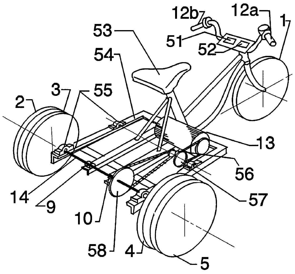
The vehicle is made up of a translating frame (chassis) and rotating members. Those mechanical elements which are rigidly attached to it (the chassis) undergo translatory motion only whereas, others have rotary motion in addition, when the vehicle is moving along a straight path.

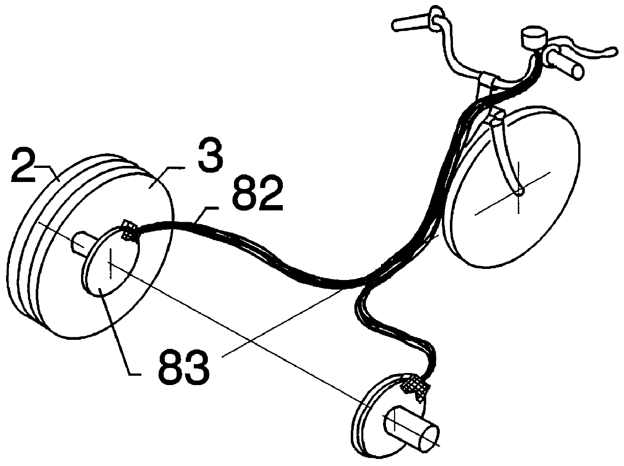
Referring to the FIG. 1, the motor (13) having a sprocket mounted on its shaft, is attached to the translating frame (54) provides motion to the rear wheels (2, 3, 4 and 5) through sprockets (56, 57, and 58) and chains. Here, the sprockets (56 and 57) are mounted on the same shaft. In this way, one obtains angular speed reduction between the motor (13) and the rear axle (14). One can provide additional rigidity to the axle (14) using two bushings (9 and 10) which are rigidly attached to the frame. One can use one heavy load bearing wheel in the place of two wheels (2, 3), which have light load bearing capacity but are cheaper, for example, those used in bicycles. The disk brakes are attached to the inner whe...


PUM


Abstract

A tricycle is driven by an electric motor supplied by batteries recharged by solar panels. Electric braking is used. The batteries and a battery charger are enclosed in a thermally insulated compartment and the batteries are kept warm in cold weather by the heat produced by the battery charger and by electric braking. The solar panels are mounted on the roof of the passenger cabin and/or on the insulated compartment and are oriented towards the sun by a stepper motor.

Description

1. Field of InventionThis invention relates, in general, to electric powered vehicles, and more specifically, to electric powered vehicles which utilize the solar energy to generate the energy required for propulsion and other uses such as powering a transistorized radio or a audio cassette recorder, etcetera.2. Description of the Prior ArtWith the decline in the fossil fuel reserves and increasing industrialization of majority of the countries throughout the world, the use of alternate sources of energy has become an urgent task. Secondly, many countries are facing traffic jams in their urban areas which have devastating effects on the health of the drivers of fossil fuel powered vehicles and also, those of the residents of those areas. This has lead to the search for the electricity powered vehicles which would not emit pollutants. The pollution problem is very severe in many of the under-developed countries where a large number of two cylinder vehicles such as scooters, three-whe...

Claims


Application Information

Patent Timeline
IPC IPC(8): B62K5/00B62K5/04B62M23/02B62M6/45B62M6/85B62M6/90
CPCB62K5/027B62M6/45B62M6/85B60L8/003B60L11/007B62M6/90Y02T10/7083B60L2200/12B60L50/20Y02T10/7072
Inventor SHARAN, ANAND M.
Owner SHARAN ANAND M
Why Eureka
Try Eureka